other public infos
on the public pages from me are also some Infos available:
Alll Users who have access on this page also have permissions to EDIT this page, feel free to add new issues/tipps or improve this page.
(the page have a page history and version control, don´t by shy to edit this page)
Updated: 19.dec.2019 Patrick.J aka DSL-man
updated: 10.March 2020
DO NOT SHARE THIS INFOS in public domain - its copyrighted (by Matthias and me), thank you.
for all Cloney Users who have the PCB Version Z17/10 mk4 cba SME (from 2017/18) please use this link : The Cloney - secret files
important is the issue on the Z card or you short -9 and 12V
the latest Version is Z19/09 Mk4 cba (you find it on rear of the Z card) for this is following issue list except my build tips which are for all versions
| ID | MatthiasIssueNr. | Issue release date | Issue | Solution |
|---|---|---|---|---|
| 1 | 29 | 19.dec.2019 | When mounting the matrix to the lower frontpanel by the ground terminals, a distance of 1 - 1.5 mm can be noticed between the matrix's surface and the frontpanel. | File down the narrow part of the bushing to at least 3 mm or less. Plan B: try a washer or 2 of them (not tested yet) Plan C: Re-drill the matrix at these two holes to the diameter of 8 mm and file down the tooth. 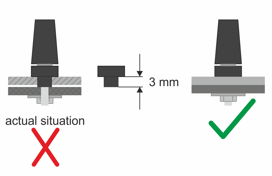 |
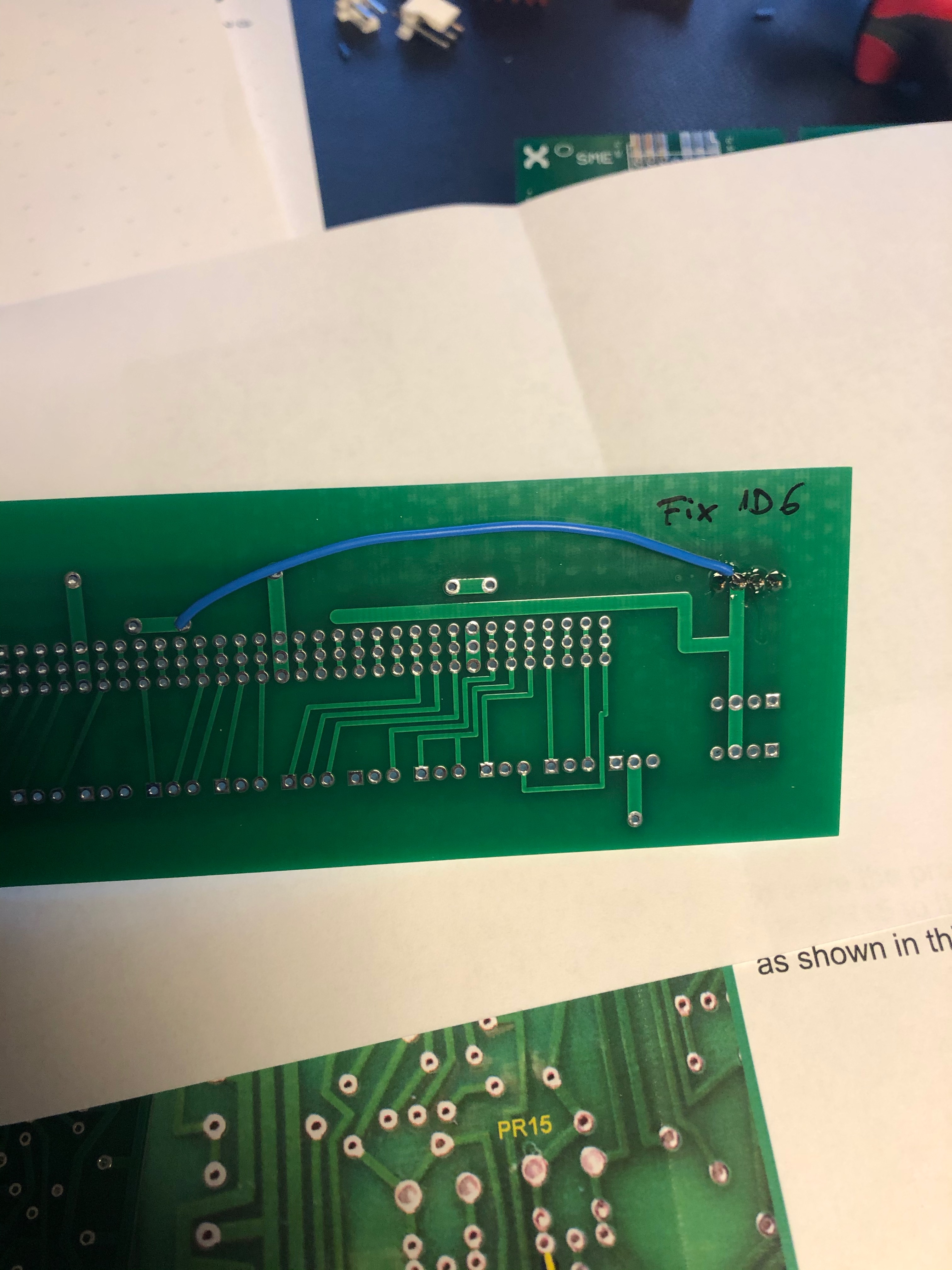
| 2 | 28 | 16.dec.2019 | At the Z board there is a link missing on the 12 V trace. The failure affects OSC 1.. |
|
| 3 | 27 | 16.dec2019 | At the Z board the captions of the presets are not printed. | See herefor the attached page of the population guide. |
| 4 | 26 | 08.dec2019 | "I meanwhile realized the EK construction manual gives no detailled information about mounting the matrix to the lower panel. So I decided to extend the manual by an additional page. Find this new page attached to this Newsletter. With this change, the actual EK construction manual now is rev. 1.24 and will be part of the next shipments (serial 078, 101, 106)." | |
| 5 | 25 | 04.dec.2019 | PCB Version: Y19/09/mk4 cba There is no trace error at the X board. It is at the Y board - I am sorry. As reported, it was already soldered by Derek before packing the Electronics-Kit. | Therefor see the attached photo. If this link is not present, solder a piece of wire to complete the trace.
|
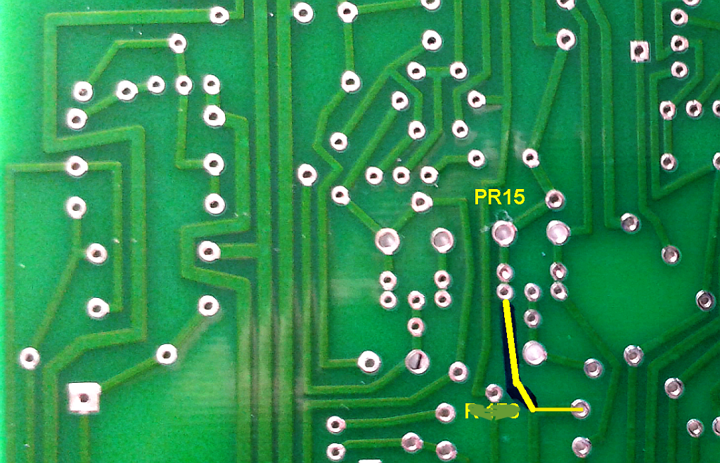
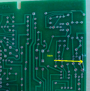
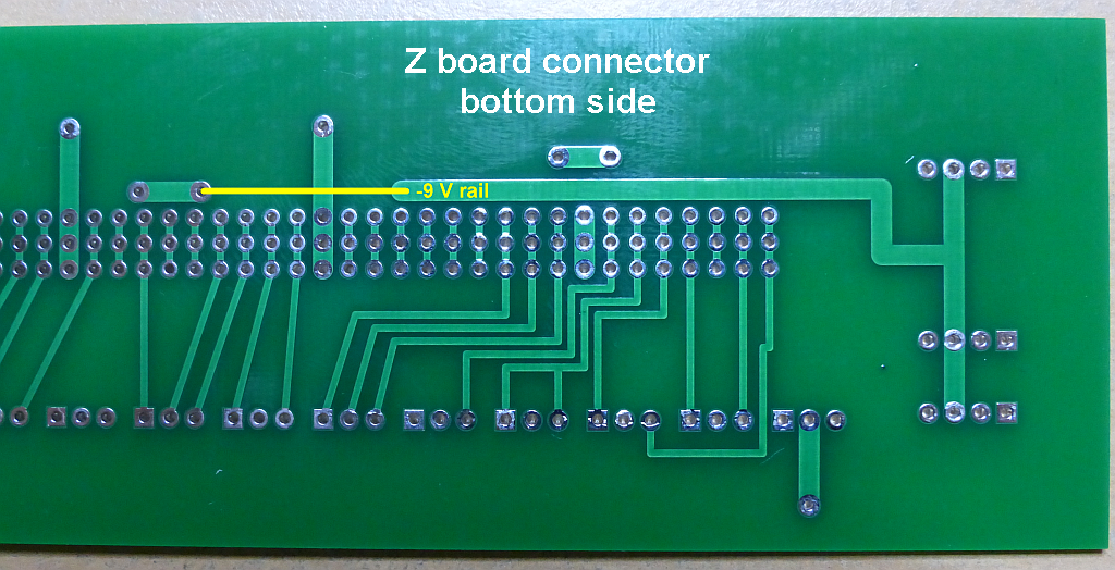
| 6 | 24 | 03.dec.2019 | There is a track error at the -9 V rail. See the attached backplane photo. | Solution: Solder a cable as shown in the picture (yellow link) to connect the right part of the -9 V rail.
|
| 7 | 22 | 03.dec | Info only: Please refer to page 2 of the Population-Guide Version 1.92 | |
| 8 | -- | 23.dec | Info: the 1K 2Watt resistor for the X board is for the PSU wiring... not on the X board pcb use 1% metal film resistors or select the 2% resistors on board X. | |
| 9 | Issue 30 | 27.dec | R 12 (PSU / earth link) The wiring diagrams were not correct since an update earlier. This causes a parasitic voltage and in some cases obviously a strange behaviour | Solution: So the next shipments will include construction manual rev. 1.26 or even a higher revision. File: |
| 10 | -- | 29.dec | howto for X card remove the Pin 4 and 8 (the connector for the 2 TIp3055) |
|
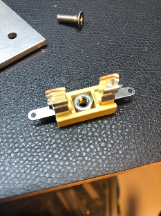
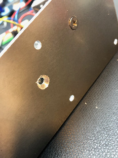
11 | use a 7mm drill that the flat screws fits flat on bottom of the PSU base plate, only as seen on the picture on right side. wide also the fuse holders with a 4mm drill that the delivered screws from the kit will fit thru the fuse holders. |
| ||
| 12 | 31 | Major Problem: | Solution: | |
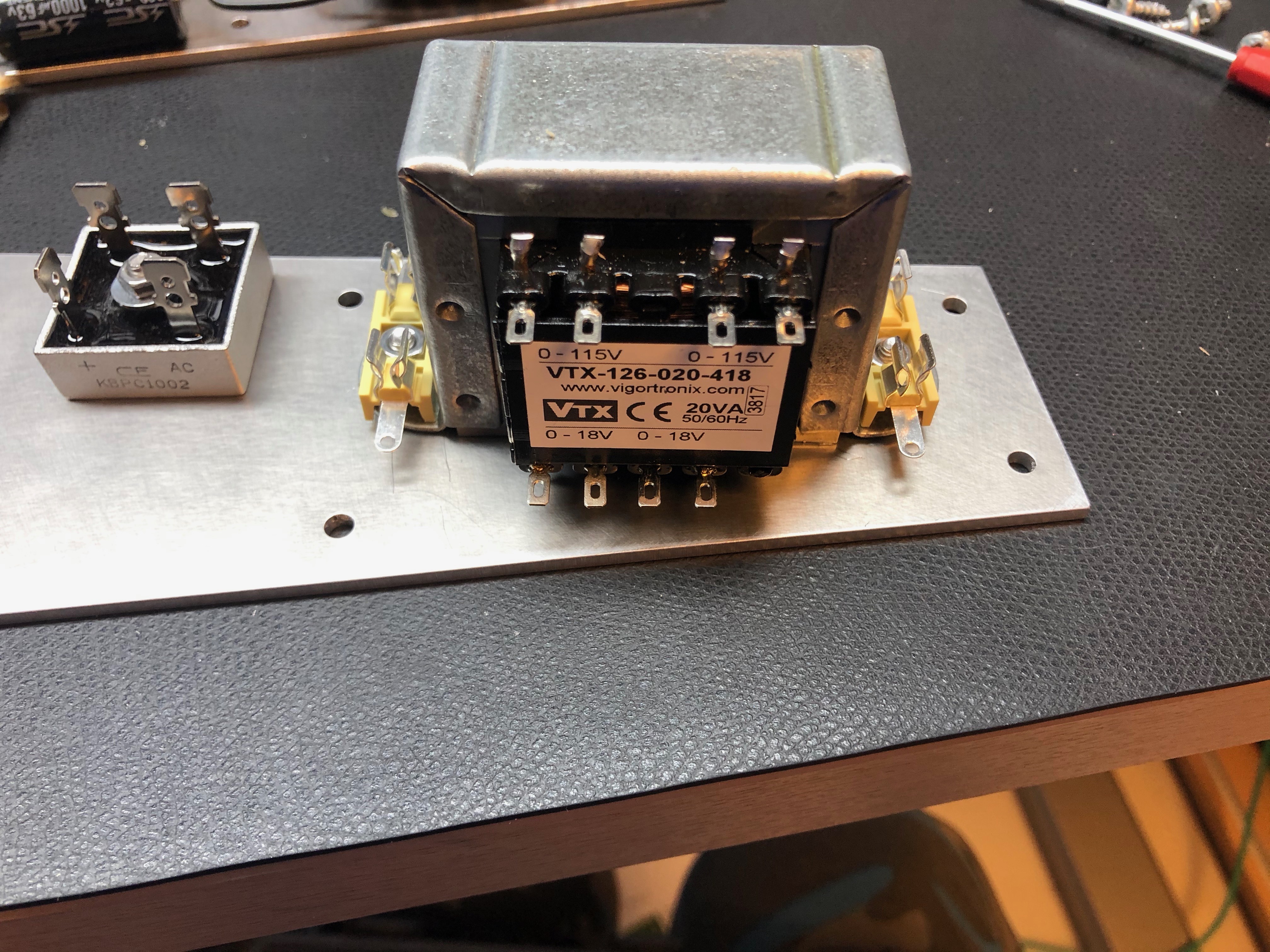
| 13 | Patrick Issue | Problem: the regulators are too hot for my experience - we waste too much energy in heat | the 18V AC transformer is "wrong" here - we have a 27V DC output after the bridge rectifier, beer we only need 15V DC. so I tried a 12V AC transformer which gives you a stable 18V DC output under load which is much better, the heatsinks are only at 22-30 degrees instead of 50C or higher. TME PART number: TS20/023 please note: you have to drill 3 holes in the PSU back plate to mount this. | |
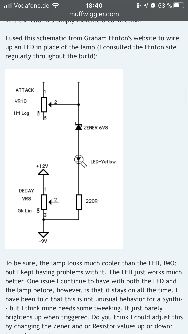
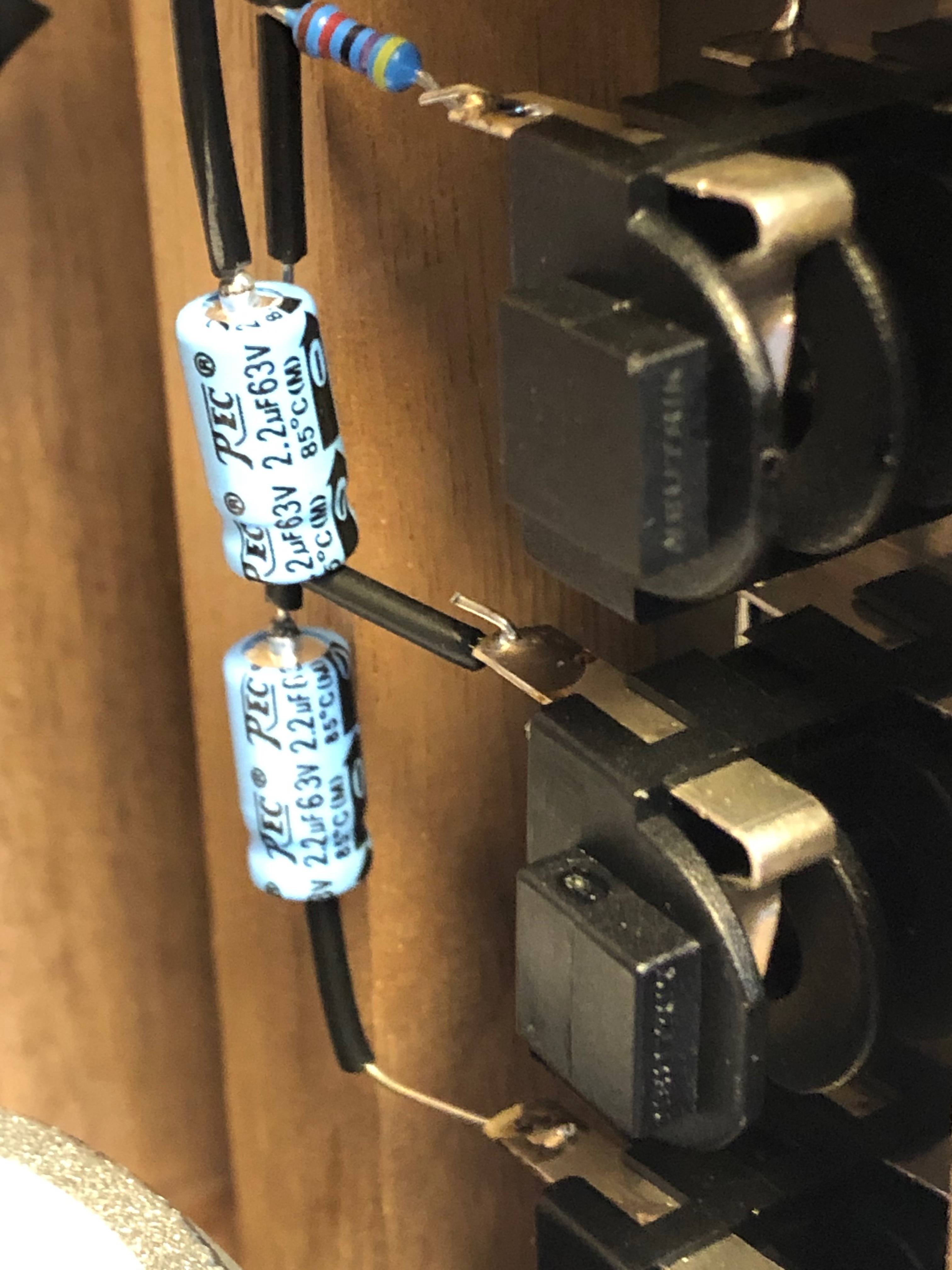
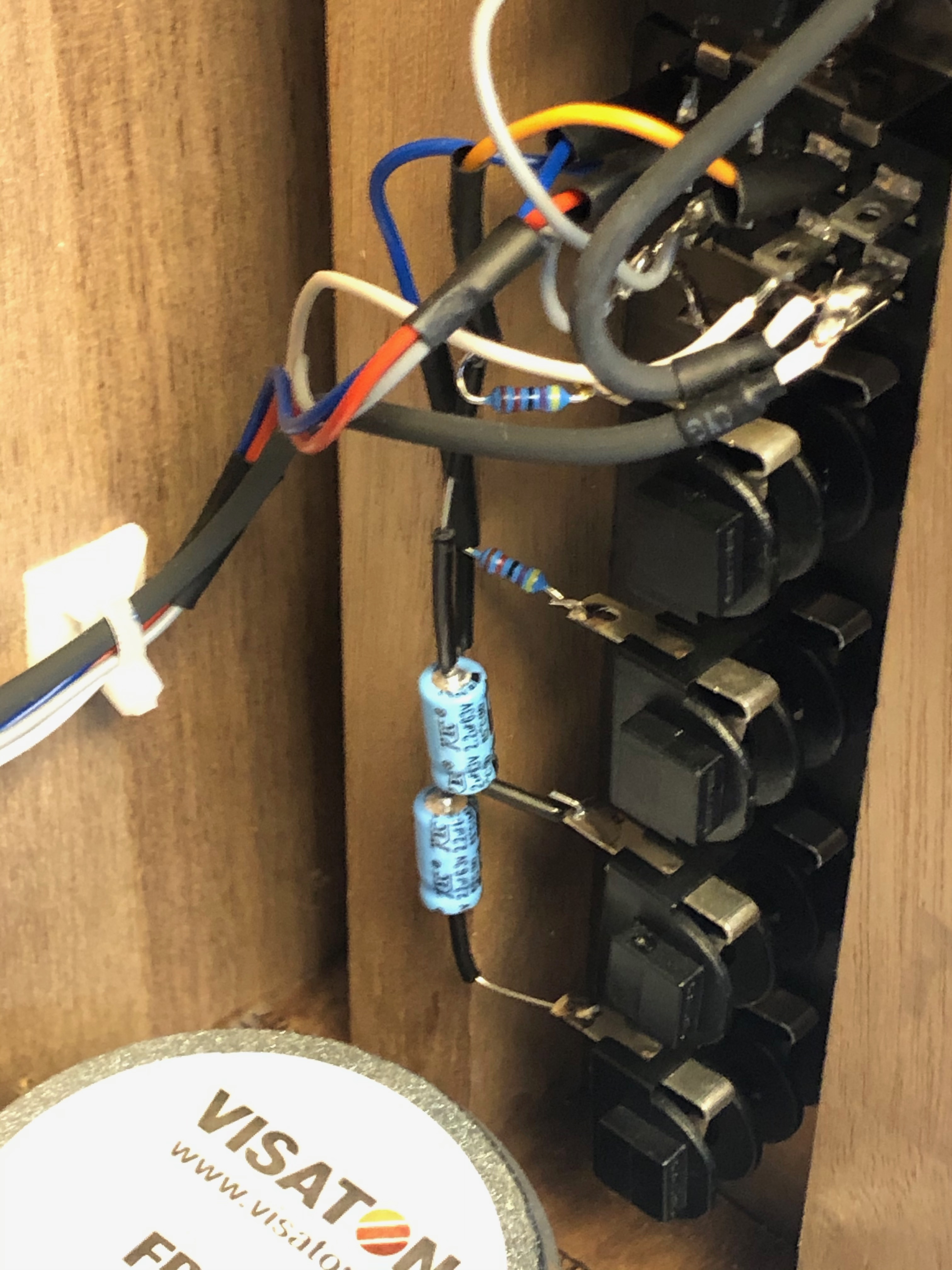
| 14 | Patricks | Problem: Envelope bleeds in VCOs | the Lamp is the root cause. it can be replaced by a LED (preferred yellow) you also Need a 6V8 zener (6.8V zener Diode and cable tube/shrink) it was tested by me and works fine. TME Led holder with included LED: 2658.8073 (mentor vendor part nr.) 6v8 zener diode: BZX55C6V8-TAP
| |
| 15 | Patrick | improvement: Buffer | http://www.portabellabz.be/synthipcbs.html Install. guide: |
Calibration (from Hinton)
SOT = select on Test or use a trimmer
1. Check Mains voltage setting.
2. Plug in Card A only.
3. PSU Switch on. Adjust PR2 for +12 volts.
4. PSU Adjust PR1 for -9 volts.
5. Plug in Cards B and C.
6. PSU Recheck +12V and -9V.
7. REVERB Adjust Pr3 so that mixing occurs above 2 on the Reverb Mix knob.
8. REVERB Check the voltage control of reverb mix.
9. O/P Adjust PR4 and PR5 for zero residual signals.
10. O/P Check the tracking of Level knobs 4-5-6.
11. ENV Set Trapezoid speed to 65Hz with PR12
12. ENV Set PR13 clockwise.
13. ENV Adjust PR7 for minimum residual signal.
14. ENV Adjust PR13 until signal just reappears, then back off to zero.
15. ENV Check that maximum On time is at least 4 seconds.
16. ENV Check that maximum Decay time is at least 15 seconds.
17. ENV Check that recycling occurs with Off set at 5.
18. ENV Check that recycling does NOT occur with Off set above 7.
19. ENV Check that Trigger functions and does not jam.
20. FILT With filter in oscillation and Frequency control on 5, set PR6 for 261Hz.
21. FILT Check that Response control gives filtering below 5 and oscillation above.
22. FILT Check the shape of the oscillating Sine wave.
23. RM Adjust PR10 for fundamental rejection on A residual signal.
24. RM Adjust PR9 for 1st harmonic rejection on A residual signal.
25. RM Adjust PR11 for fundamental rejection on B residual signal.
26. RM Adjust PR8 for 1st harmonic rejection on B residual signal.
27. RM Check for frequency doubling when both inputs are the same.
28. I/P Check both channels for correct gain on both Hi and Lo inputs.
29. OSC1 Adjust PR17 for best sine wave shape.
30. OSC1 With Frequency on 6 set PR15 for 261Hz.
31. OSC1 With Frequency on 8 add R290 (sot) to achieve 2088Hz.
32. OSC1 Recheck last two steps.
33. OSC1 Check both waveforms.
35. OSC2 Set PR20 half-way.
36. OSC2 Pad shape resistors R227/R228 to achieve correct shapes.
37. OSC2 With Frequency on 6 set PR19 for 261Hz.
38. OSC2 With Frequency on 8 add R291 (sot) to achieve 2088Hz.
39. OSC2 Recheck last two steps.
40. OSC1/2 Adjust PR20 to achieve oscillator tracking to 2kHz.
41. OSC3 Pad shape resistors R261/R262 to achieve correct shapes.
42. OSC3 With Frequency on 8 set PR21 for 63Hz.
43. NOISE Select a (transistor) diode for good bandwidth and level.
44. NOISE Adjust PR2 for around 3 volts p-p noise.
45. NOISE Check the operation of the noise colour control.
46. METER Set signal zero on the meter itself and check operation.
47. METER Adjust PR14 for control voltage zero.
48. JOYSTICK Adjust vertical for equal excursions on meter.
49. JOYSTICK Adjust horizontal for equal excursions on meter.
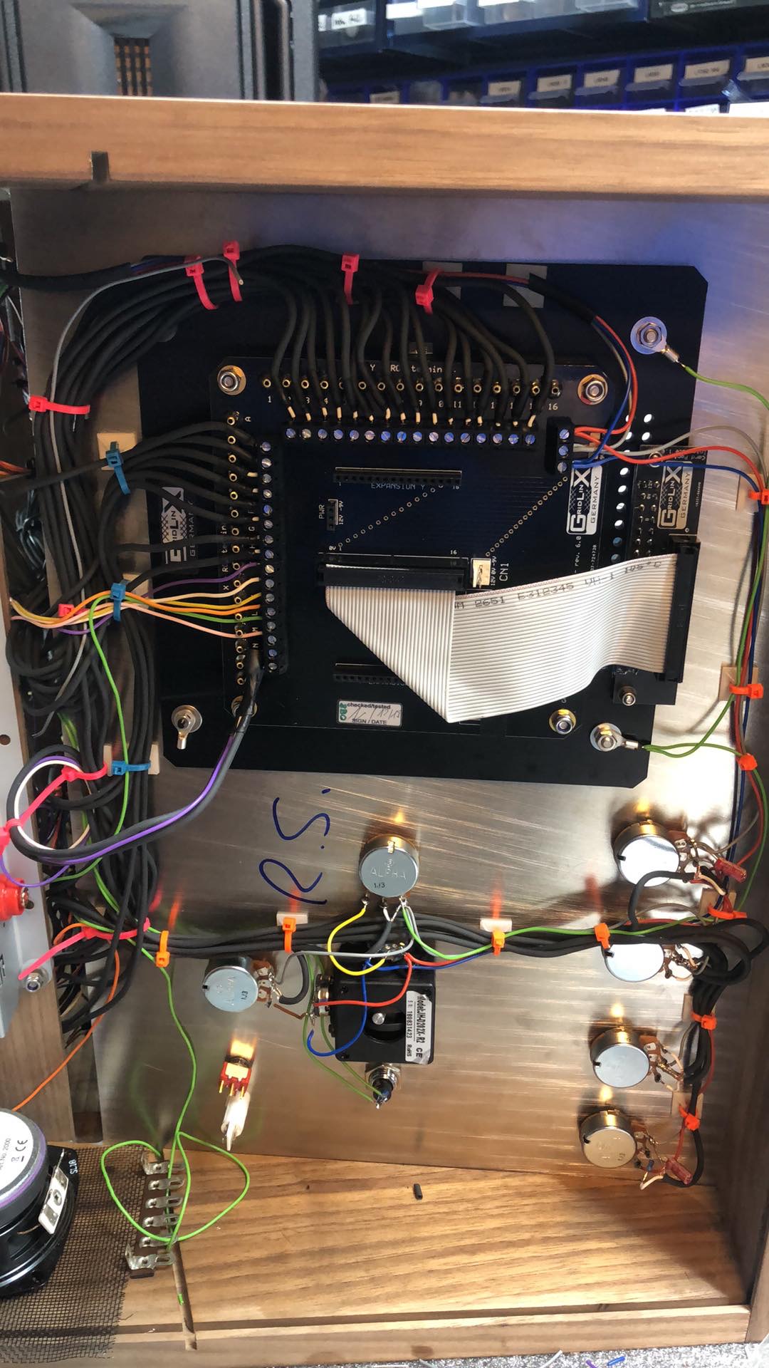
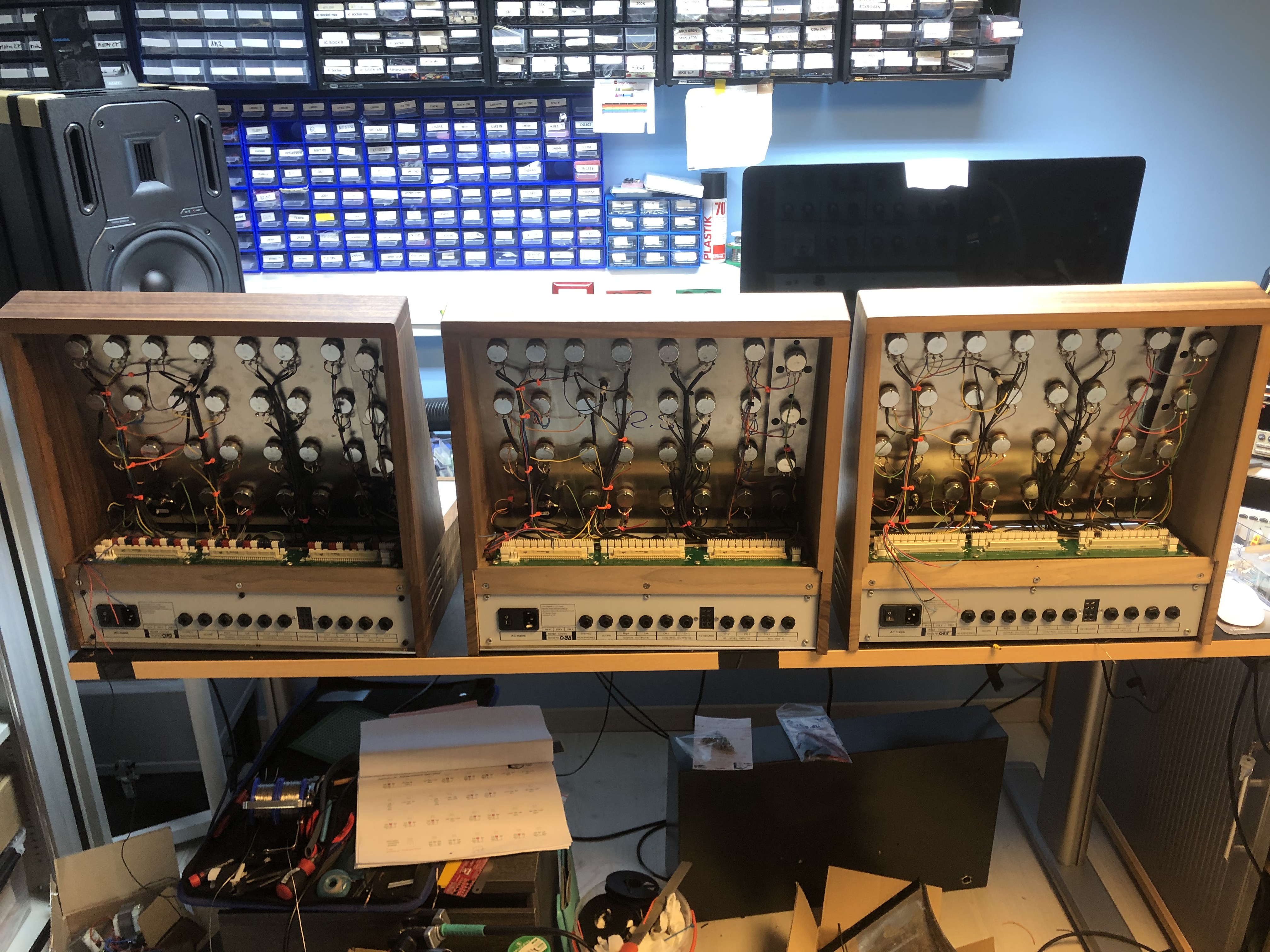
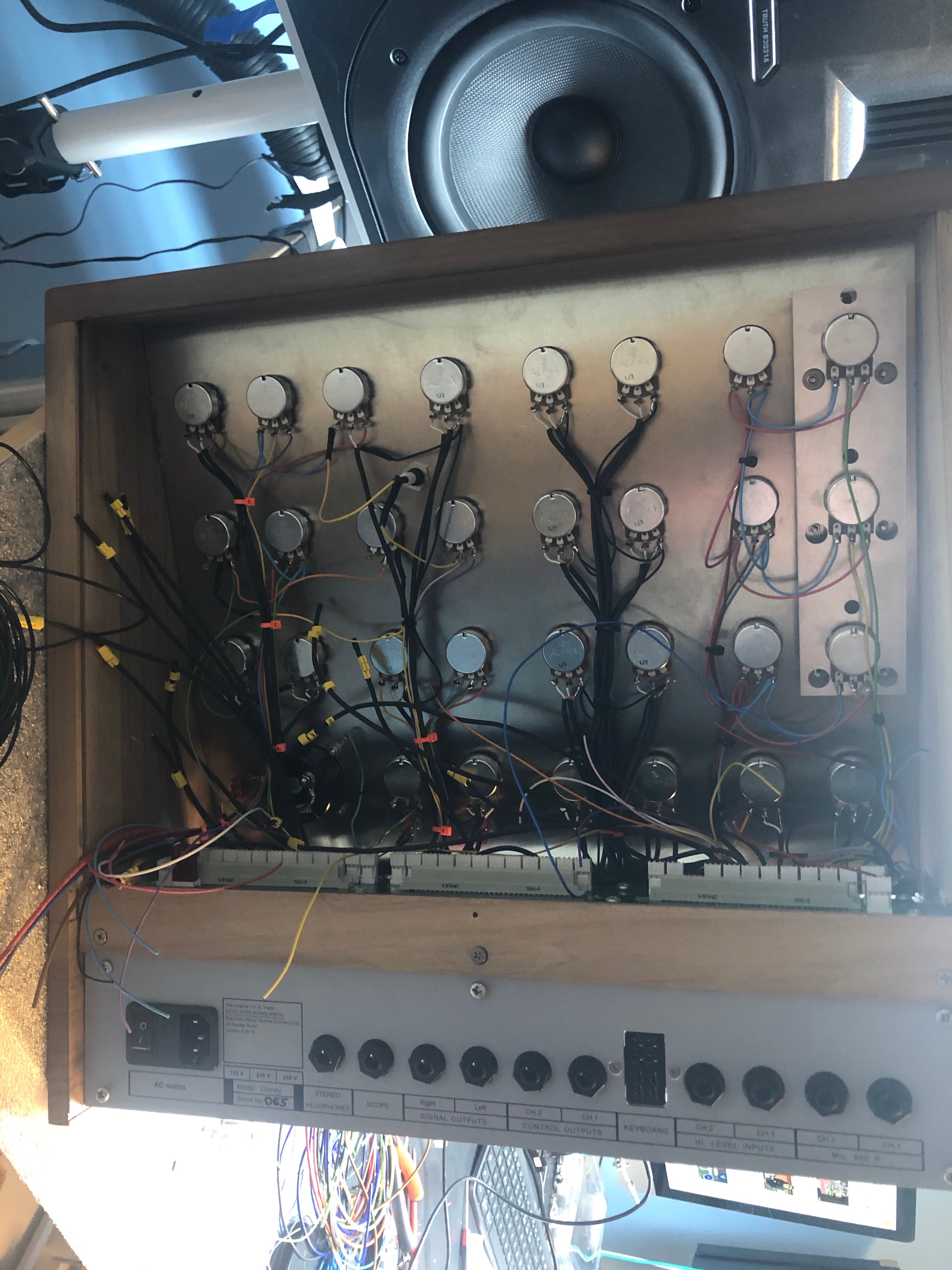
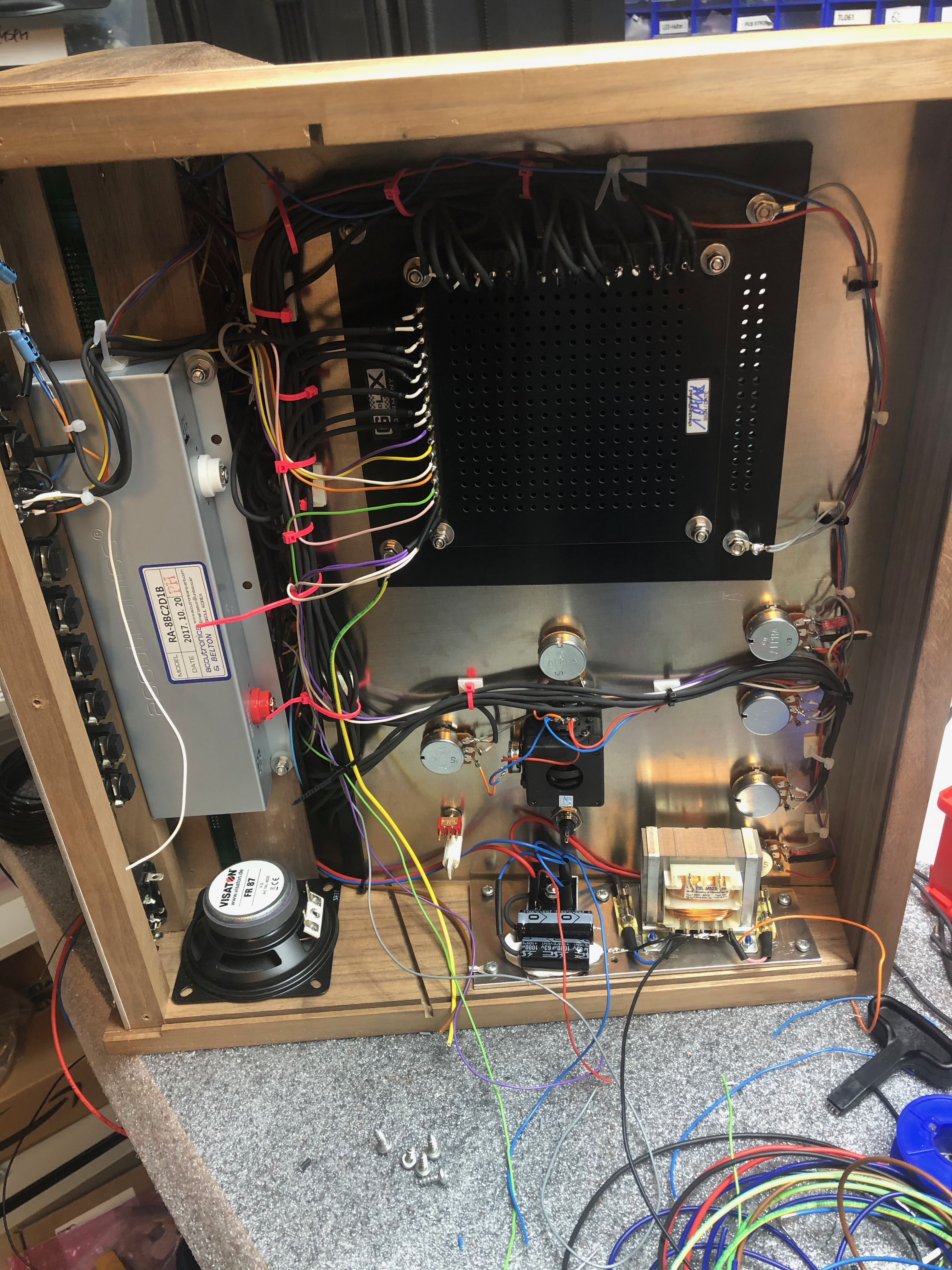
my own build tips, here are some pictures of my 5 builds:
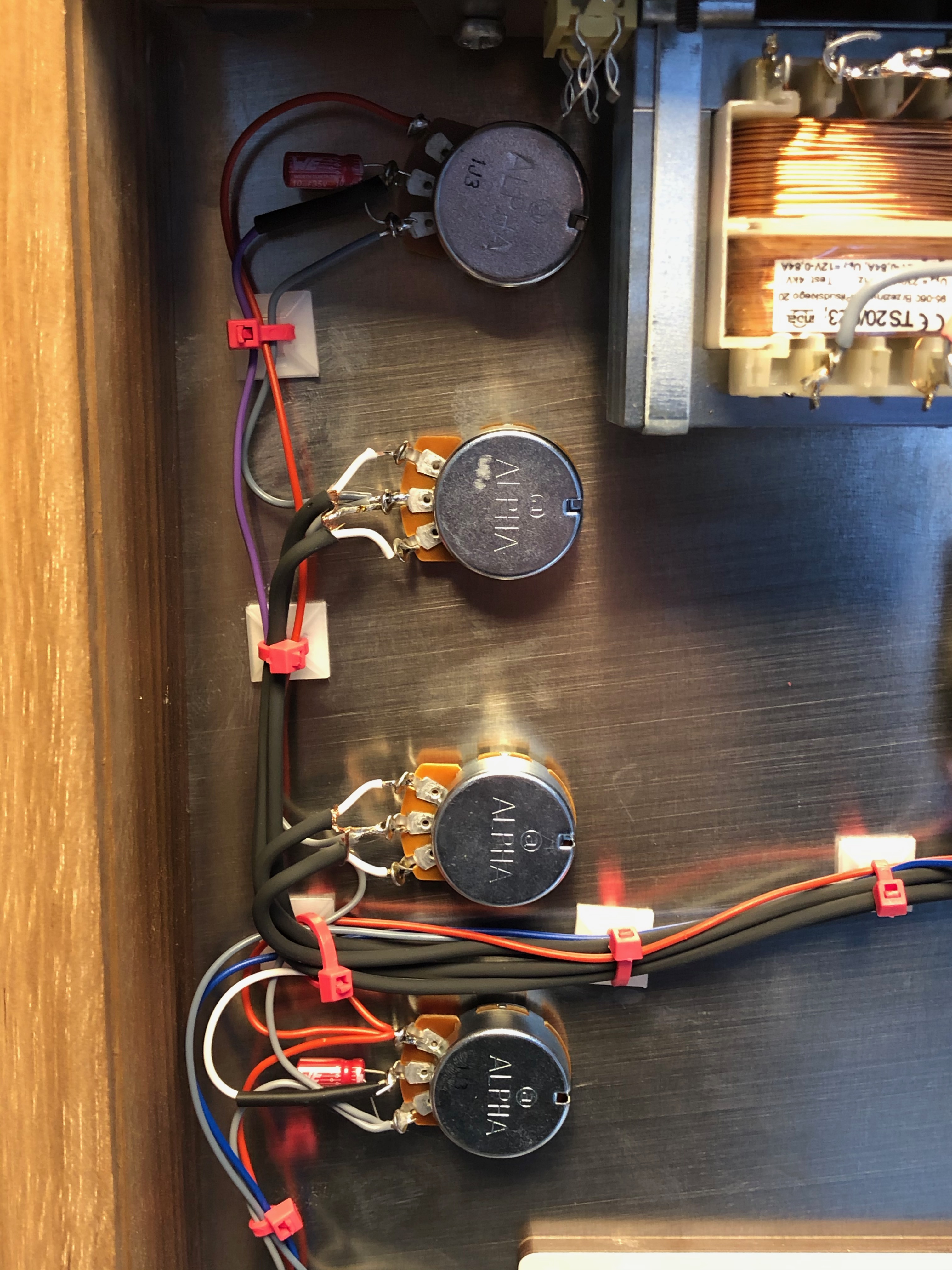
lower panel:
Upper panel, mostly shielded cable:
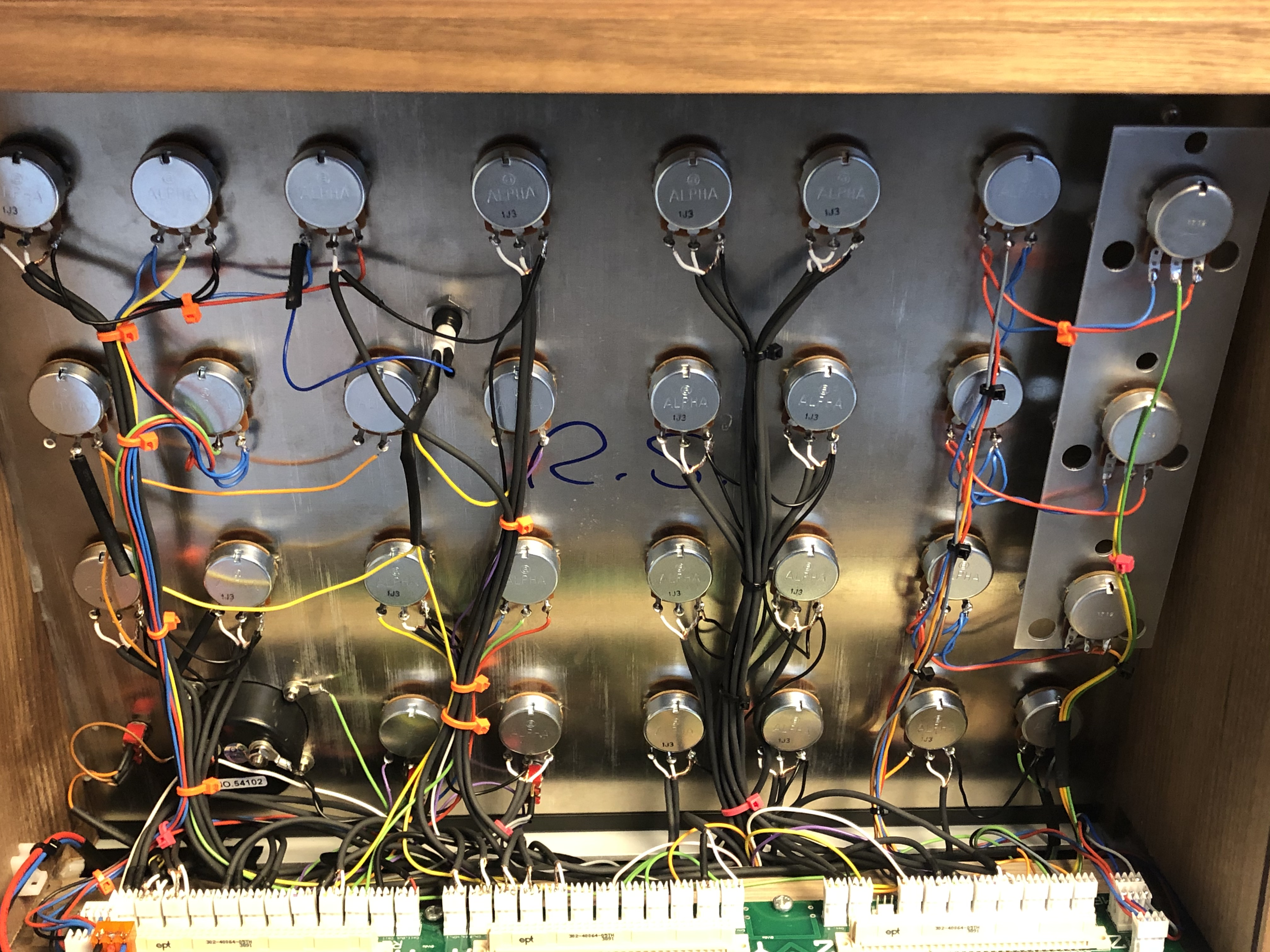
picture from an older Matrix version:
mx own Cloney with Ghielmetti
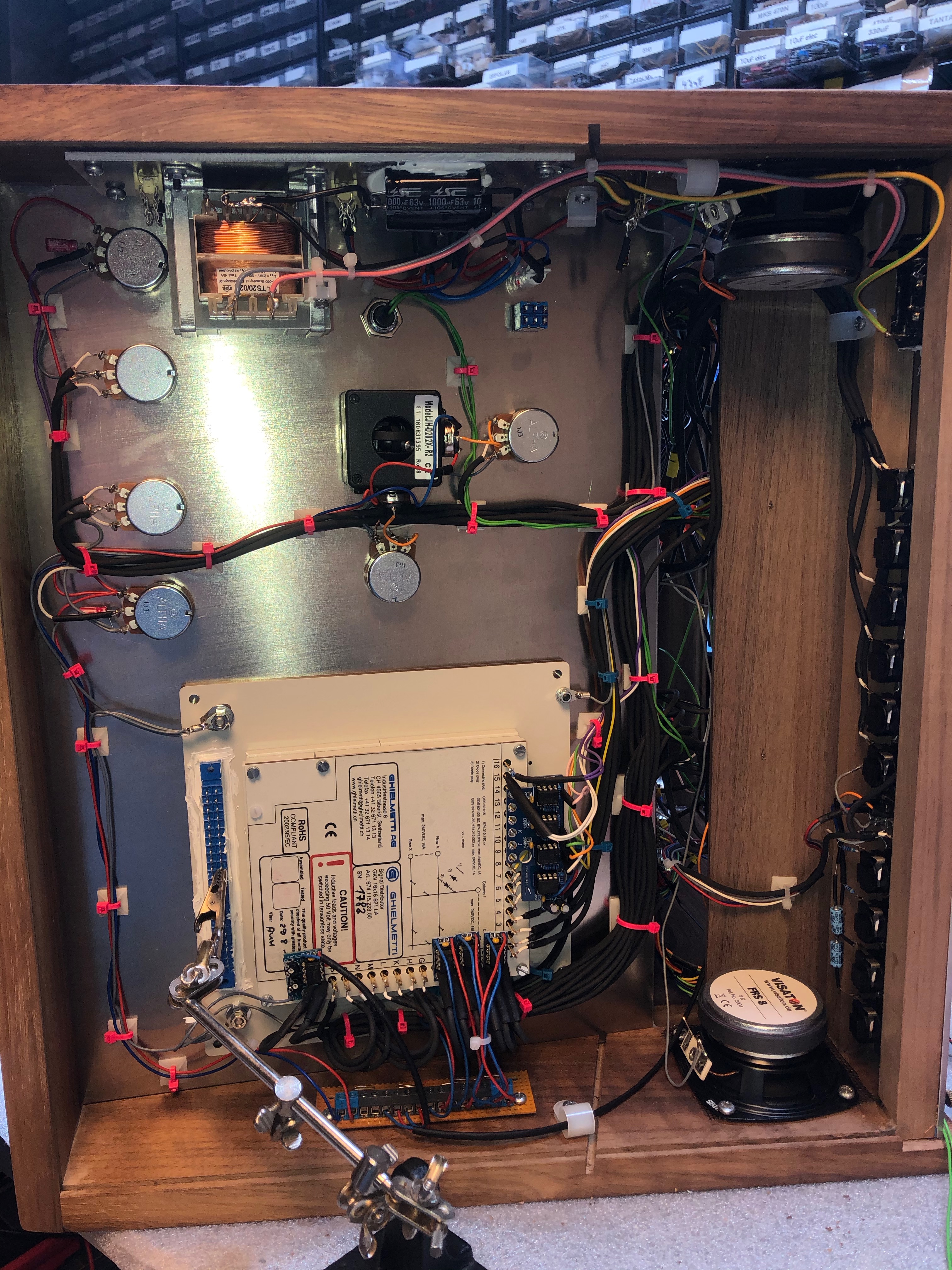
latest 2019 Matrix Version