Manual:
https://help.mikrotik.com/docs/display/UM/Chateau+5G+ax
open:
To remove the cover, first remove the rear screw, then carefully separate the front seam at the top/bottom using a Spudger or similar DIY repair tool, until the front cover lifts off. I came across this YouTube video for opening the Chateau LTE12, which has the same outer casing as the 5G model.
5G Model:
"With the external antenna connections, you will unlikely need to connect anything leading to modem ports A2 or A3 as these are for 5G band n79 (4.4-5GHz), which is currently only used in a few Asian countries such as China, Hong Kong and Japan."
"All the ports ANT0 through to ANT7 on the modem are mobile data connection ports. The Wi-Fi connection ports are separate on the main board"
"Connect one set of antennas to ANT0+1 and the second set of antennas to ANT6+7."
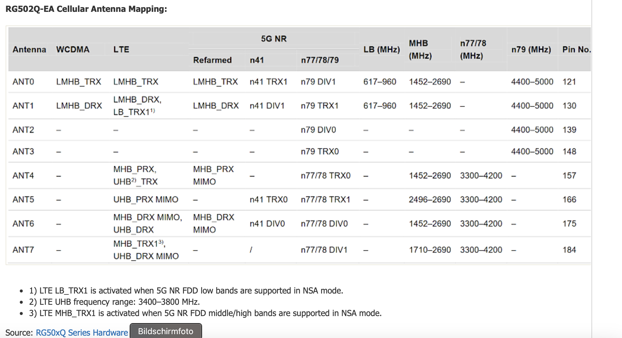
Frequency bands in table
LB = Low Bands - All bands up to 960MHz
LMHB = Low/Middle/High Bands - All bands up to 2690MHz
MHB = Middle/High Bands - All bands from 1452MHz or 1710MHz to 2690MHz
UHB = Ultra High Bands - Bands from 3400 to 3800MHz
4G LTE Antenna connections
TRX = Transmit/Receive - Antenna #1 for 2x2 or 4x4 MIMO
DRX = Diversity Receive - Antenna #2 for 2x2 or 4x4 MIMO
PRX MIMO = Primary Receive #2 - Antenna #3 for 4x4 MIMO
DRX MIMO = Diversity Receive #2 - Antenna #4 for 4x4 MIMO
TRX1 = LTE Antenna #1 paired with a 5G NSA connection over FDD LMH bands (see table notes 1 & 3 above)
5G NR Antenna connections
TRX(0) - Transmit/Receive - Antenna #1 for 2x2 or 4x4 MIMO
DRX(0) - Diversity Receive - Antenna #2 for 2x2 or 4x4 MIMO
TRX1 - Transmit/Receive #2 - Antenna #3 for 4x4 MIMO
DRX1 - Diversity Receive #2 - Antenna #4 for 4x4 MIMO
source: https://confusedbird.com/thread-119-post-1151.html
Original wiring:
Ant2 = port A4
Ant1= port A5
port A0 = right side chassis internal Antenna
port A6 = upper side antenna soldered on right side (upper antenna on chassis)
port A7 = upper side antenna soldered on left side (upper antenna on chassis)
port A3 on X pcb soldered
port a2 on x pcb bottom
Changemanagement:
- A4 zu A0 (Antenna swap ) A0 to external connector
- A5 zu A1 (Antenna swap) A1 to external connector