...
| ID | Issue | Fix | date | fixed version |
|---|---|---|---|---|
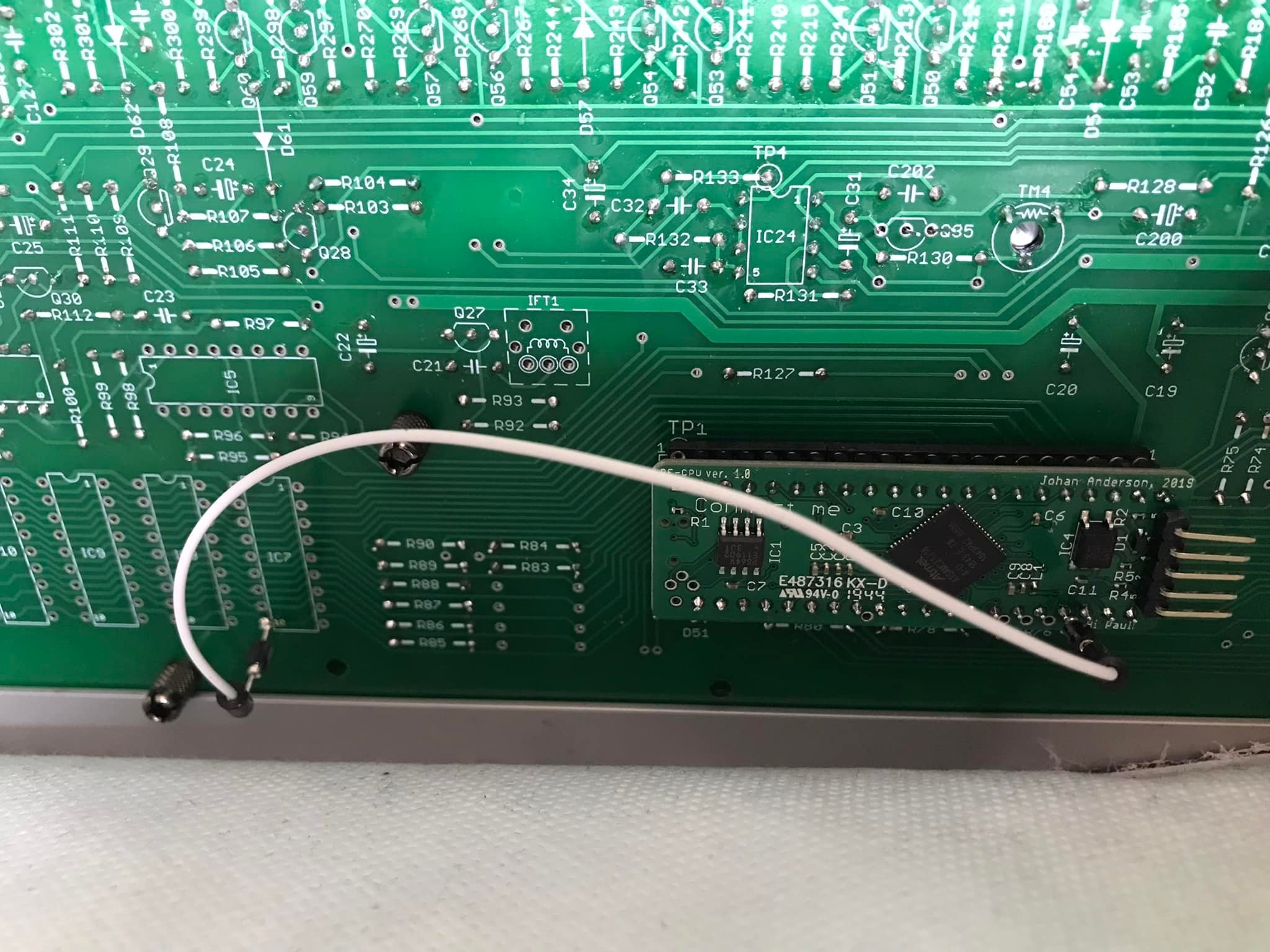
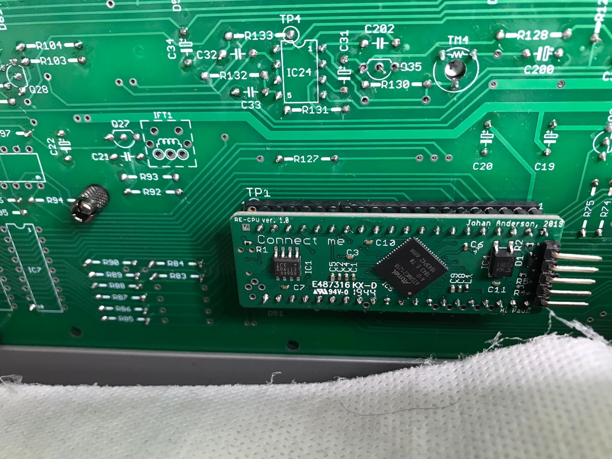
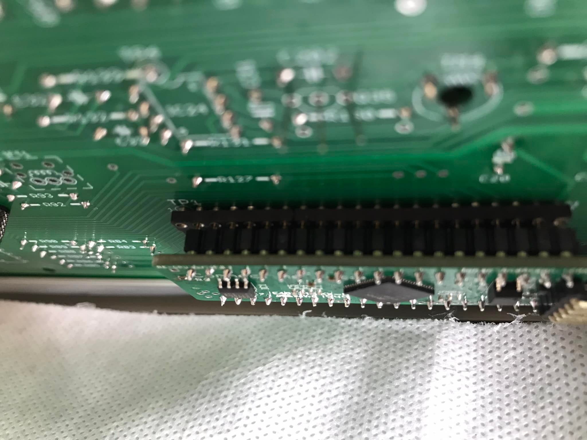
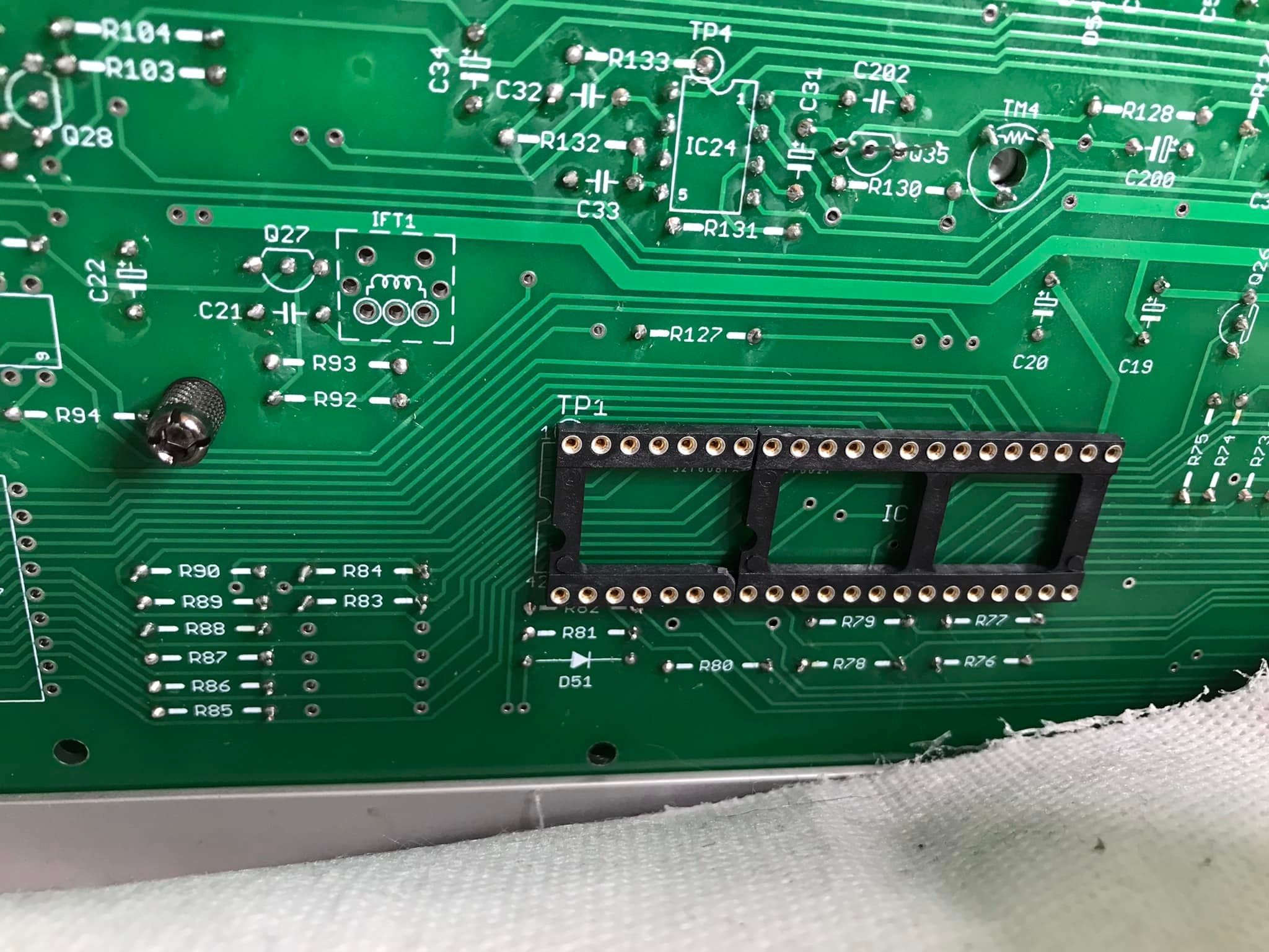
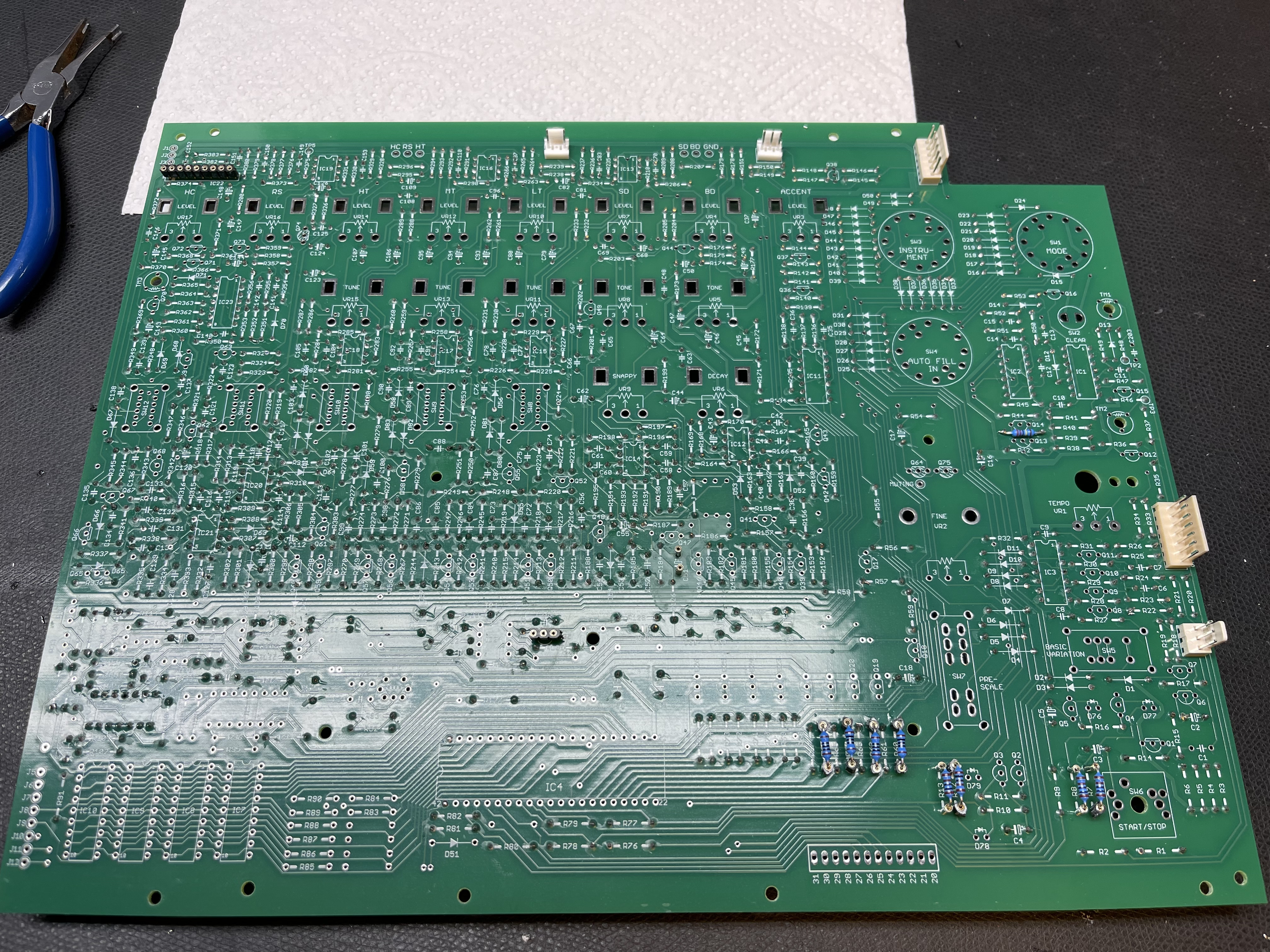
| 1 | CPU mounting | As you can see you also need to do a jumper wire between the solder point marked A on the pixie cpu and pin 10 (!WE pin) of *any* of IC 7,8,9 or 10 (they’re all connected to the same signal)
| 01/2022 | |
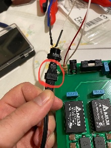
| 2 | PSU | Do not fit the DC jack on the PSU circuit board. Its not used and it is not wired correctly. use a cable for the jack as shown for example
| 01/2022 | |
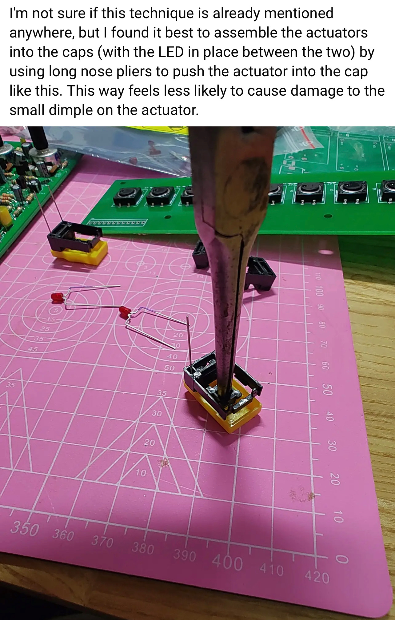
| 3 | Tactiles /caps install | heres a tip about the installation of the tactile caps:
| 01/2022 | |
| 4 | MIDI WIRING |
| 11/2022 | |
| 5 | Silkscreen wrong |  | 11/2022 | |
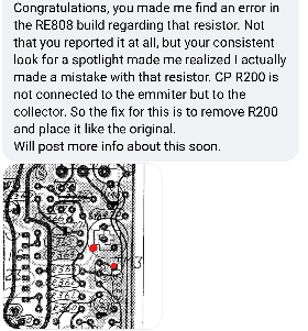
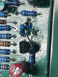
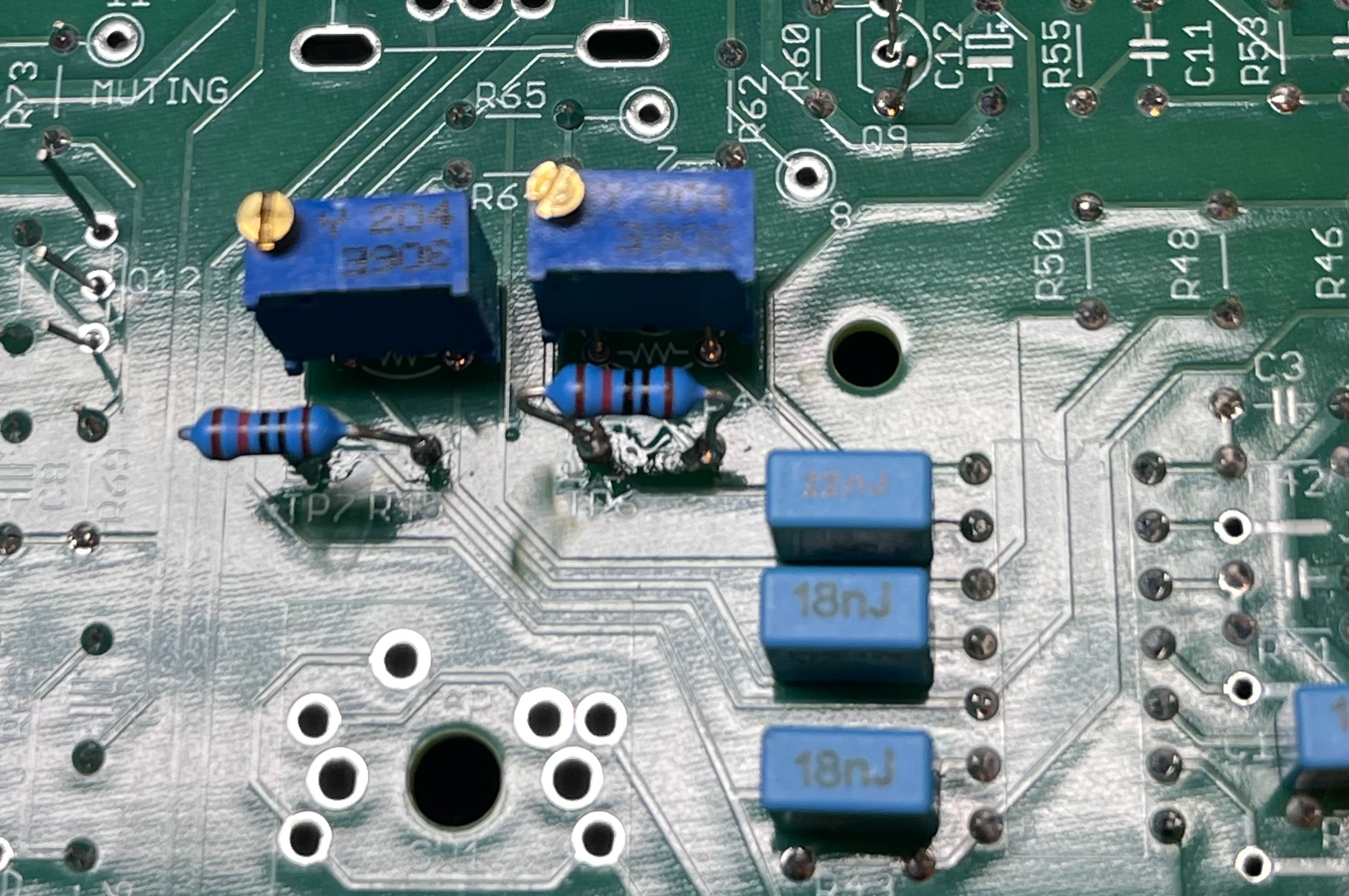
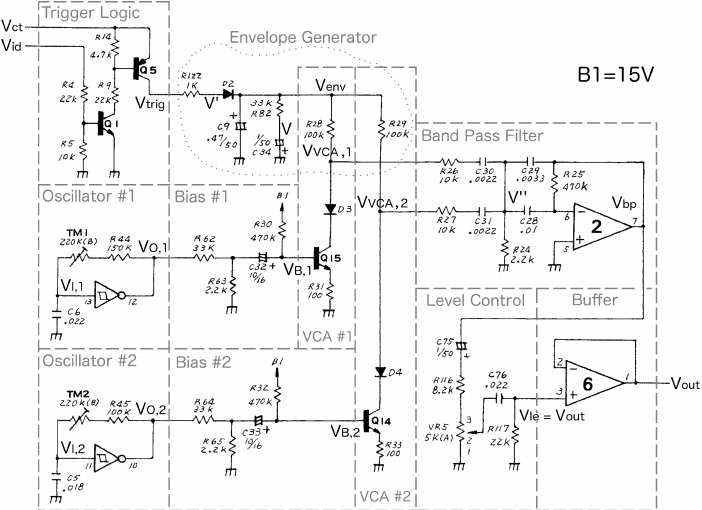
| 6 | Mainboard resistors - handclap |
in case you have the trimmer on solder side (recommended) Add the R200 (10K) as shown in the left picture above at the 2 red dots.
| 11/2022 | |
| 7 | guide /tip | for the voice board: first install all 1/8watt resistors on bottom of the pcb R1-9 are 1/8w or the switchboard do not fit use MLCC caps there and no IC socket. for IC1. when you have a solder frame: install the flat Trannys and ic sockets before you install the other parts for mainboard use for the noise transistor and muting trannys - ic socket pins to swap/change the trannys install good trimmers from nearside instead cheap trimmers from component side - better calibration possible | 11/2022 | |
| 8 | Transistors - sequencer failure | use sockets for the muting transistors. some users reported issues in combination with the pixie CPU, boot/start problems. the muting Transistors affect this - you can remove this. | 1.Dec.2022 | |
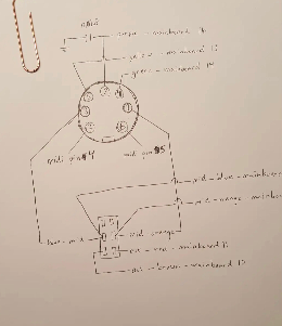
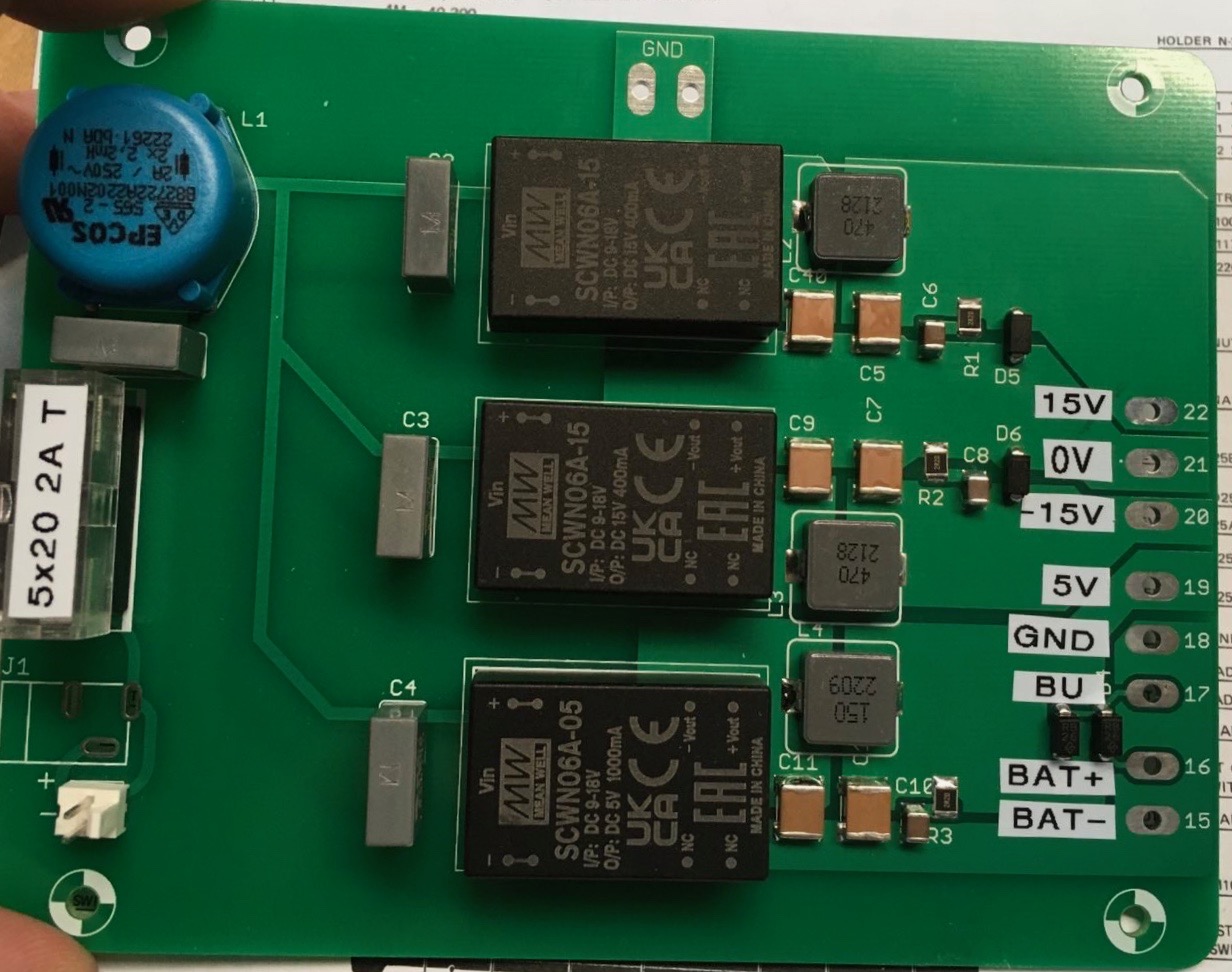
| 9 | Power Pinout |
credits by Martin.J.K - Thank you | 02.Jan.2023 | |
| 10 | general | install good trimmers on back side (solder side) - for easier calibration install the BA662 clone on solder side - in this was you can use a socket install the muting JFETS and noise Transitor on solder side for easier swapping install R333 on solder side to give you the opportunity to replace this with a trimmer (50k) to change the handclap sound.. | 02.Jan.2023 | |
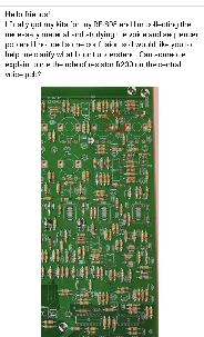
| 11 | bugfix | install a jumper as shown to get your 808 working as designed
| 03. Jan.2023 | |
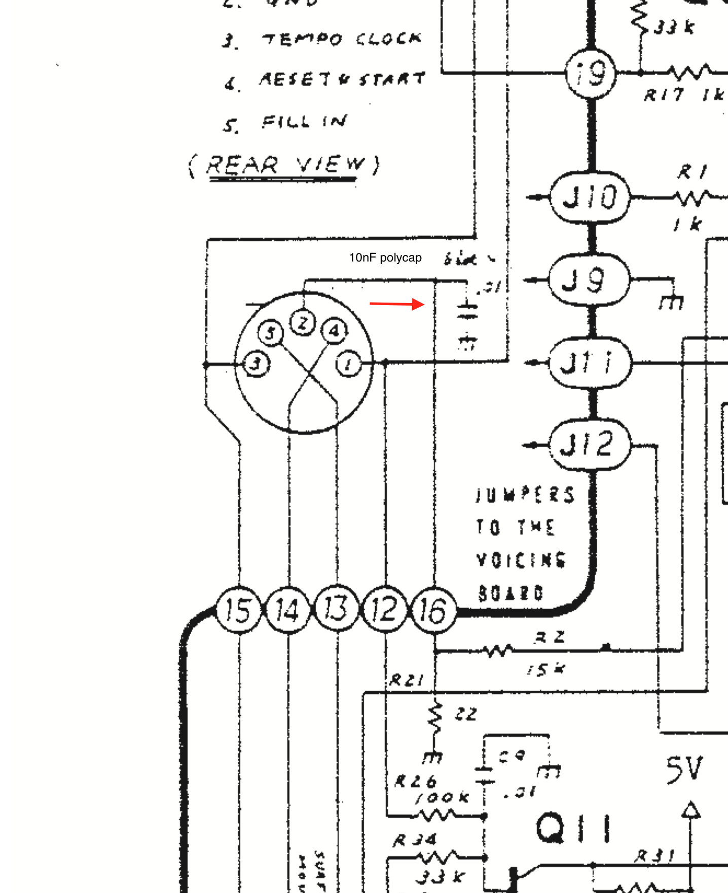
| 12 | capacitor on Sync jack | install a 10nF polyester cap or bipolar electrolyte cap at the sync jack or on the pcb
| ||
| 13 | clock calibration fix | remove C203 on mainboard (39nF) or your clock can't be calibrated in case you can't reach 120hz by trimmer end, install a 2M2 resistor in parallel on R43 | 04.Jan.2023 | |
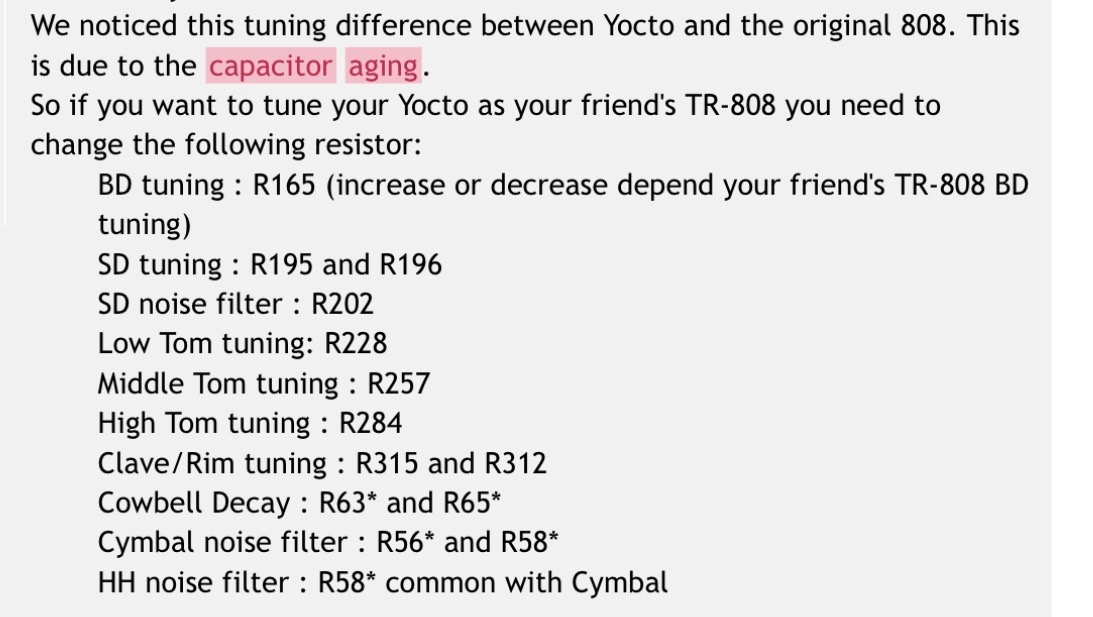
| 14 | calibration/mod |
Hi tom noise level = R273 BassDrum Endless/Extended Decay -- replaced R170 (470k) with 370k resistor in series with a 100k potentiometer. then i set the potentiometer to the 'sweet spot', where the extra decay sounded best to me, and measured the resistance of the 370k resistor plus the resistance of the potentiometer setting. on my Yocto, 445k was the nicest value for self-oscillating/extreme decay source: https://www.e-licktronic.com/forum/viewtopic.php?f=18&t=143 | 02.April 2023 | |
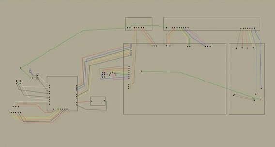
| 15 | wiring | some help.. found on FB
| ||
| 16 | ||||
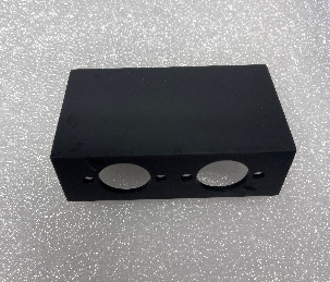
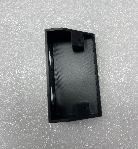
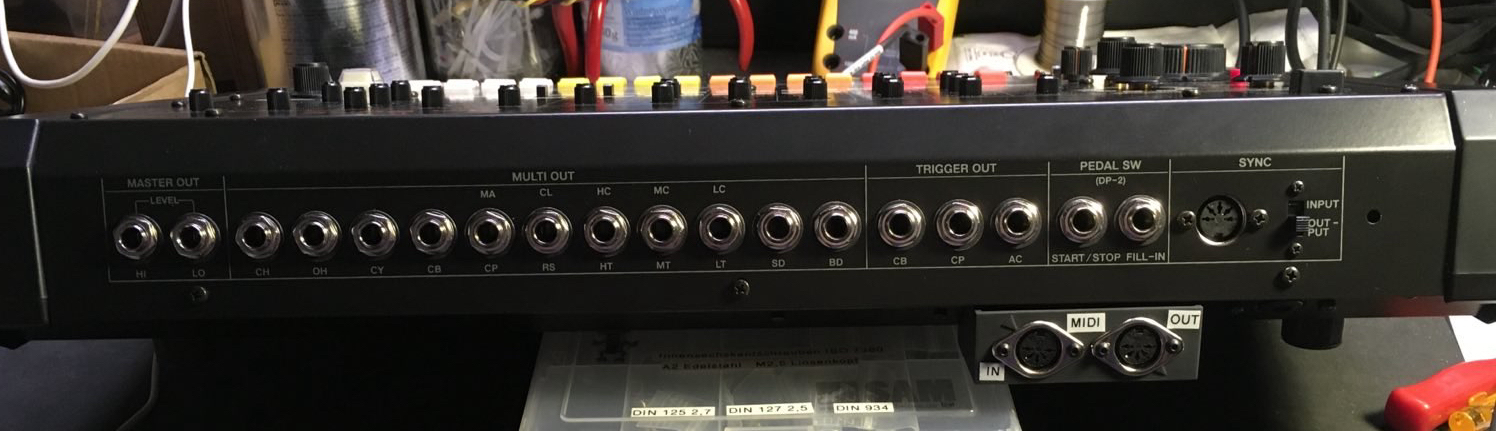
| 17 | MIDI connection MOD | the 3D printed part is available in my shop https://www.diysynth.de/spezial-re-808-parts/re-808-midi-anschluss-3d-druck.html or print it myself (Resin preferred) just use 2 screws to mount this at the typenumber plate holes at the rear and drill a small for the MIDI cables.
| ||
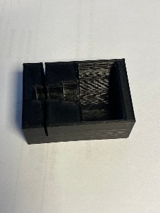
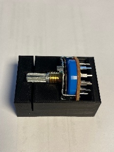
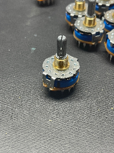
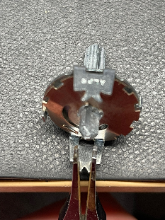
| 18 | 3D Print tool rotary switch | this tool make things easier. just drop the rotary switch inside and its easy to saw the switch to the exact given length available in my shop : https://www.diysynth.de/spezial-re-808-parts/re808-schaltersaegehilfe-3druck-teil.html
| ||
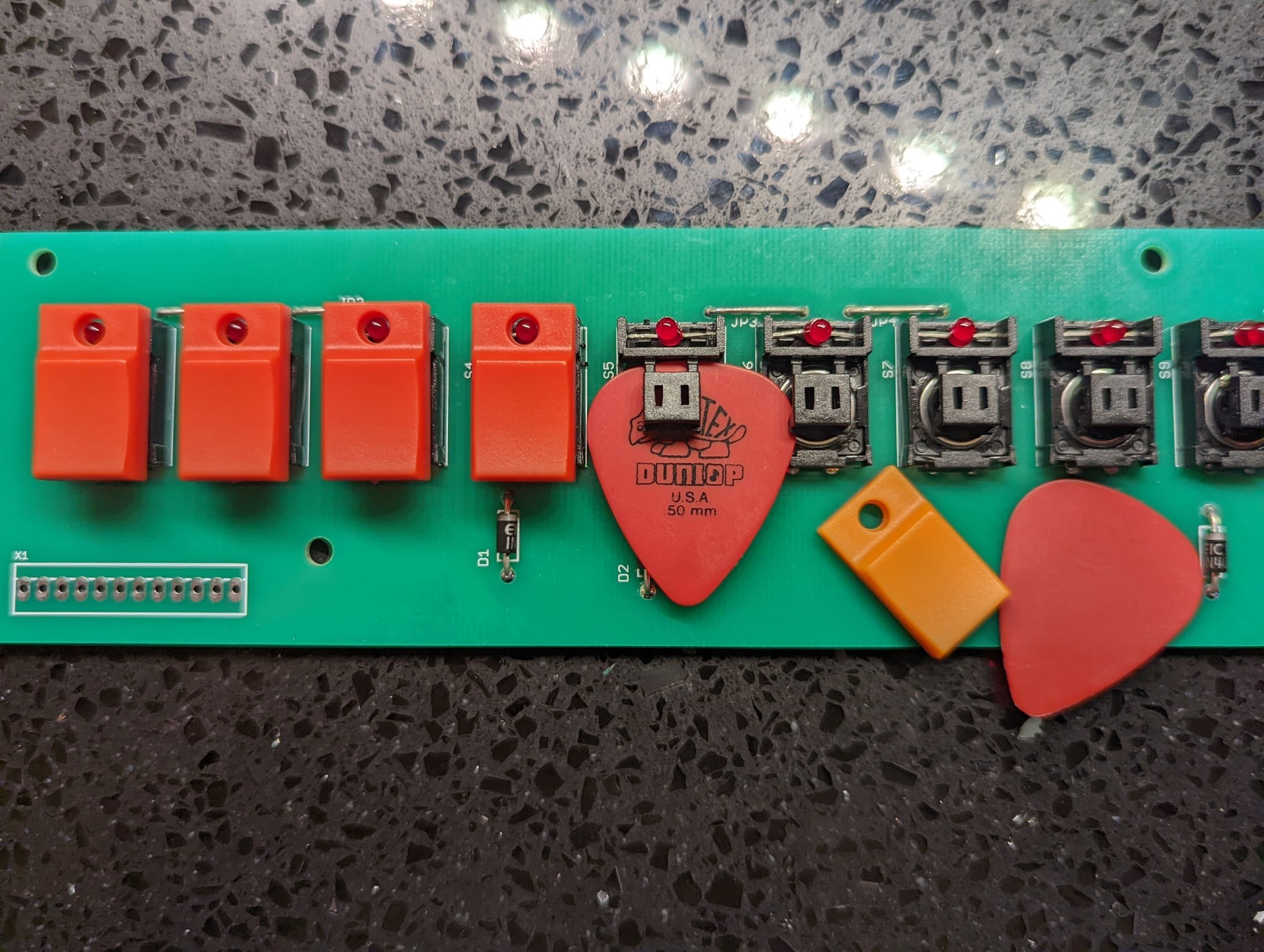
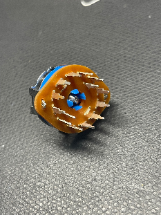
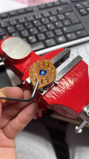
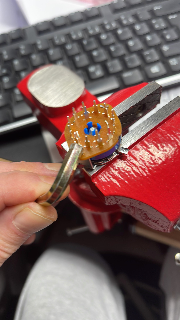
| 19 | Tip Rotary Switches | for much easier rotary switch assembling, use this knowledge PLUS the ALPS assembly guide, my infos are a additional tip how to remove and bend the tabs. Background: we dont need the upper part of the D shaft switches and we don't need the lower part of the knurled switches. for the D shaft switches you can bend the tabs at the bottom for removal as close you can - because we dont need the upper part - put the upper part (metal) in the trash bin.
for the knurled switches you can cut the pcb on bottom to remove the bottom part without bending the tabs, after you have removed the pcb - you can much easier bend the tabs !!!
after you proceed the other steps as described in the guide , you have to bend back the pins which hold the bottom part and upper part. I used here 2 tools and a hammer. in first step I punched with the smaller hex. and the hammer and later with the bigger hex. and a hammer.
| ||
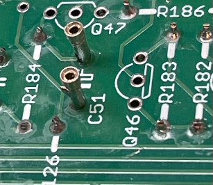
| 20 | recommend Mods for Clap and Snare | remove R333 and install a 50K trimmer from solder side - this adds the opportunity of changing the Clap frequency/bandpass Install a header for the Noise Tranny of the PCB Solderside - you can try different Noise transistors of your choice (less white noise at the snare, gain stage between handclap and Snare, a loud Handclap is wrong, too much white noise at the snare is wrong) forget the 133mV AC measurement of the noise Tranny - the important thing is the spectrum of the noise. use a transistor tester (peak tech for example to get the correct polarity or use the datatsheets) Furthermore: (highly recommend) you change c51 from 0.47uF to 0.68uF (or up to 1uF) to get more reverb/room on the Snare. use milled pins on the solderside for testing the value. Only do this mod when you are lucky with the snare sound except the reverb part is too small (personal choice) its not recommend to do this mod until you have found a good noise transistor otherwise you have too many variables.
| 02.April 2023 | |
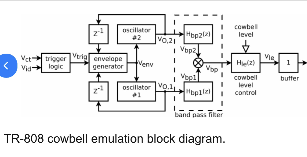
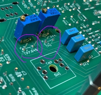
| 21 | Cowbell bugfixing | in case your cowbell is out of the trimmer range while calibration 800hz/540hz install in parallel to R44 a 10K resistor and the same for R55 (add a 10K in parallel) since we connect a scope there, let enough space to clip the probe there.
in case you have failures in the cowbell, here's a good page: visit http://frisnit.com/roland-tr-808-cowbell-rebuild/
 | 02.April 2023 | |
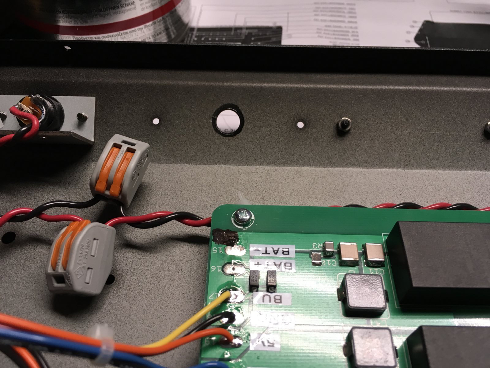
| 22 | Grounding /wiring | make sure you have a groundcable from the 2 Jackboard pcbs to your DC-DC PSU- otherwise the sequencer do not start I recommend a cable from the sync jack ground to the Dc-DC psu GND pads too, the 808 case is powder coated and you can't get a true earth there without scratching/removing the paint. some users get a buzz/clickinmg sound by touching the case or metal parts.. that's the reason - you need a solid ground from the case and jackboard pcbs to the PSU. | 02.April 2023 | |
| 23 | Cymbal Mod | source: https://www.modwiggler.com/forum/viewtopic.php?t=264016 change :The modification involves changing C40 (in the middle branch next to the 33k resistor) from 1µF to 100nF Raising C41 gives a longer decay- (not tested by me) Technical paper: tr_808_cymbal_a_physically_informed_circuit_bendable_digital.pdf | 04.April 2023 | |
| 24 | general tip | mount the DIN jack from inside of the Case - don´t install the DIN socket thru the metal case, in case of trouble shooting its much easier with the wiring - otherwise you have to disconnect/desolder some cables. | 06.April 2023 | |
| 25 | general | Here are few pictures, how I installed LED resistors on sockets, to change easily the brightness of the LEDs.
|


...