TTSH hardcore builders guide (specially rev.1)
update: 01.October2014 - jumpers, speaker workaround for testing
The first TTSH
i has build "few" TTSH in last month..
the first TTSh was build with zthees Builders Guide and works fine, but its not effective to solder section after by section.
from my second and other TTSHs was build by this TTSH on I built them after these steps:
- add both jumpers, kybdCV/GND and near the ferrite beads
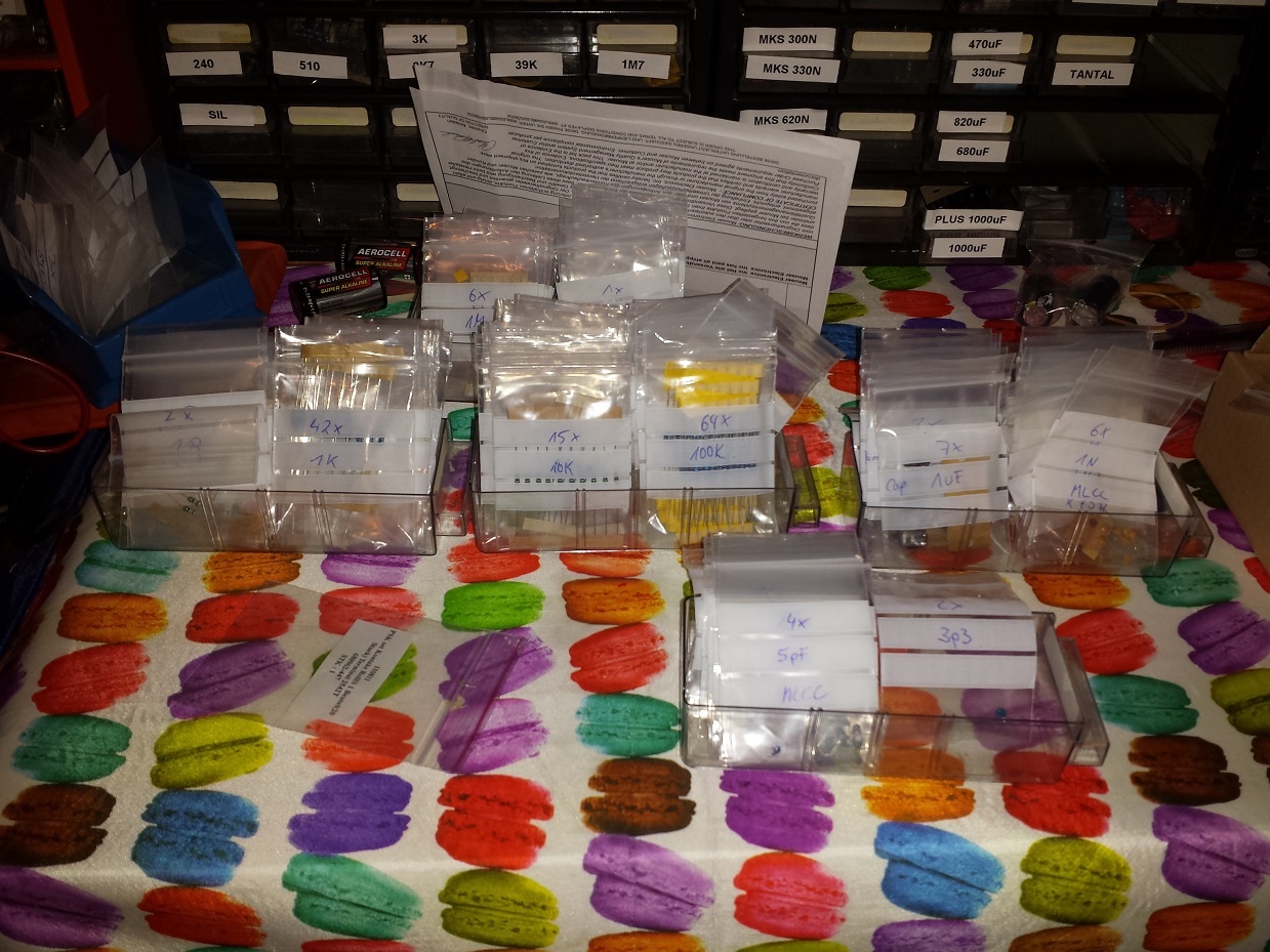
- sort sort out all resistors in values: 1R - 999R, 1K - 9K, 10K-99K, 100K-999K, 1M-22M , same with capaciators.
- take a label/sticker on places where you have MODS/bugfixes like c20 cap, noise mod etc..
- take put the TTSH pcb on 25-30mm spacer spacers (use the BD236/BD237 holes too for spacers) you have to mount a spacer on each pcb side of the spacer - pcb so you can turn the pcb for soldering..
- build the complete VCO- Subboards (so you dont don't have to look all the time for missing resistors resistor points on the main pcb all the time)
- solder all IC sockets on both sides of the pcb sides (LED IC on the other side of the pcb side)
- solder all voltage connectors (MTA´s) in the powersections and powersection, key cv, speaker etc.
- put all resistors in place on the main pcb, beginn start with the highest ammounts like over amounts; (more than 60 x 100K) ... if you'll have completed nearly 80% complete, its easier to place the rest and it'll be easier now to put the rest in place section by section.
- solder all resistors from the top
- turn pcb and cut all pins/legs shorter - so this way you can solder all pins/legs in one step..
- if you have a VCO voltage regulator from nordcore, put a tape over the 100nF/10uF caps near the power MTA header.
- Capaciators - begin with 100nF c0g for the audio path, followed by 100nF for the rest,and then all the other caps.. keep Attention pay attention on filmresistors, i the filmresistors... I use film caps (wima) for the VCF near matched trannys and which makes the Filter sounds very sound really good.
- solder all caps from the front/rear.. keep attention on the C20 cap
- put all diodes and trannys in place and trannys ..(keep pay attention on c20, max noise fix, bridge instead of 2n5172 in clock, in VCF matched, sont mount the Amp. cooling blocks
- fill put all the LM301 in the IC-sockets
- create build the VCO header connection for all 3 VCOs..
- unmount the 25-30mm spacer spacers and replace them with the final 12mm spacers and screws..
- solder all faders, at first begin with 1 solderpoint on every side, put the frontpanel on the pcb and check the fader orientation. - alternative: bend one leg on each side and solder one point only
- check the orientaion
- finally solder all the final soldering for all faders..
- Jacks: solder on each corner 1-2 jacks, and 3 in middle, place the panel and then solder this few jacks.them
- then place all jacks, bring put the panel on top and mount the nuts on the jacks in the corners and , then turn the panel, now you can point solder all the jacks..
- switches.. unmount the panel, put all switches in place and mount the panel, turn the panel/pcb .. the switches fall in place, solder a bit.. turn the panel and check the orientation on the frontpanel, if it is good , final solder finally ( please check the mechanical function of the switch before you mount them, sometimes you have faulty switches and its hard to desolder thisthem..)if you have a VCO regulator, build this and put this on the powerheader and drill a hole in pcb and mount a spacer
- *update 01.October 2014 : if you want to test the TTSH with speakers but without the headhone jack wiring add a jumper to TN/ T or RN/R otherwise your speaker won't work.
- build the power wiring cables and solder the internal DC-DC adapter..
- initial check : disconnect all sections, check with DMM the voltage near DC-DC adapter with a DMM .
- if you have a VCO regulator, build it, put it on the powerheader, drill a hole in the pcb and mount a spacer,calibrate the regulator to 14,6V
- test and calibrate the TTSH - good luck