Project
Projecttitel: Stereo 1176D clone
Status: IN PROGRESS
Startdate: 02.03.2023
Duedate: 01.04.2023
Manufacture link:
PCB:
hairball audio 1176 D version - which is the mnats version
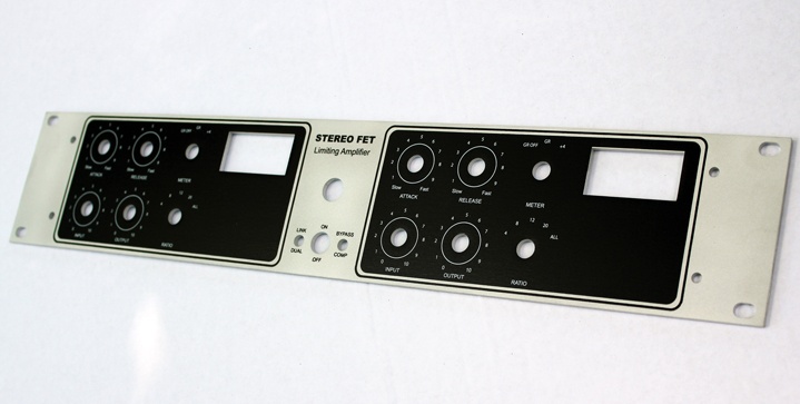
Panel and Case:
https://collectivecases.com/?product=stereo-1176
BOM and Schematic:
Hairball Audio offer part kits/half kits for a stereo version, you have to add the PCBs too.
| ID | Part | add. info | link | price netto | price with all fees |
|---|---|---|---|---|---|
| 1 | case | case | https://collectivecases.com/?product=stereo-1176 | 150 USD | |
| 2 | pcbs | hairball PSU x2 | 20 USD | ||
| 3 | part kit pcb |
| https://www.hairballaudio.com/catalog/parts-store/old-style-fetrack/stereo-fet-compressor-rev-ad-bundle | 475USD | |
| 4 | XLR | XLR’s – Nuetrik D series connectors (part # Neutrik NC3FD-L-1-B & Neutrik NC3MD-L-1-B) 2 of each !!! | |||
| 5 | IEC power inlet | IEC – Schurter 6200.2100 (Mouser Part # 693-6200.2100) | look for better version with filter | ||
| 6 | PSU PCB | PSU pcb from hairball | only one needed !! - check capacitor sizes RM7.5mm | 10USD | |
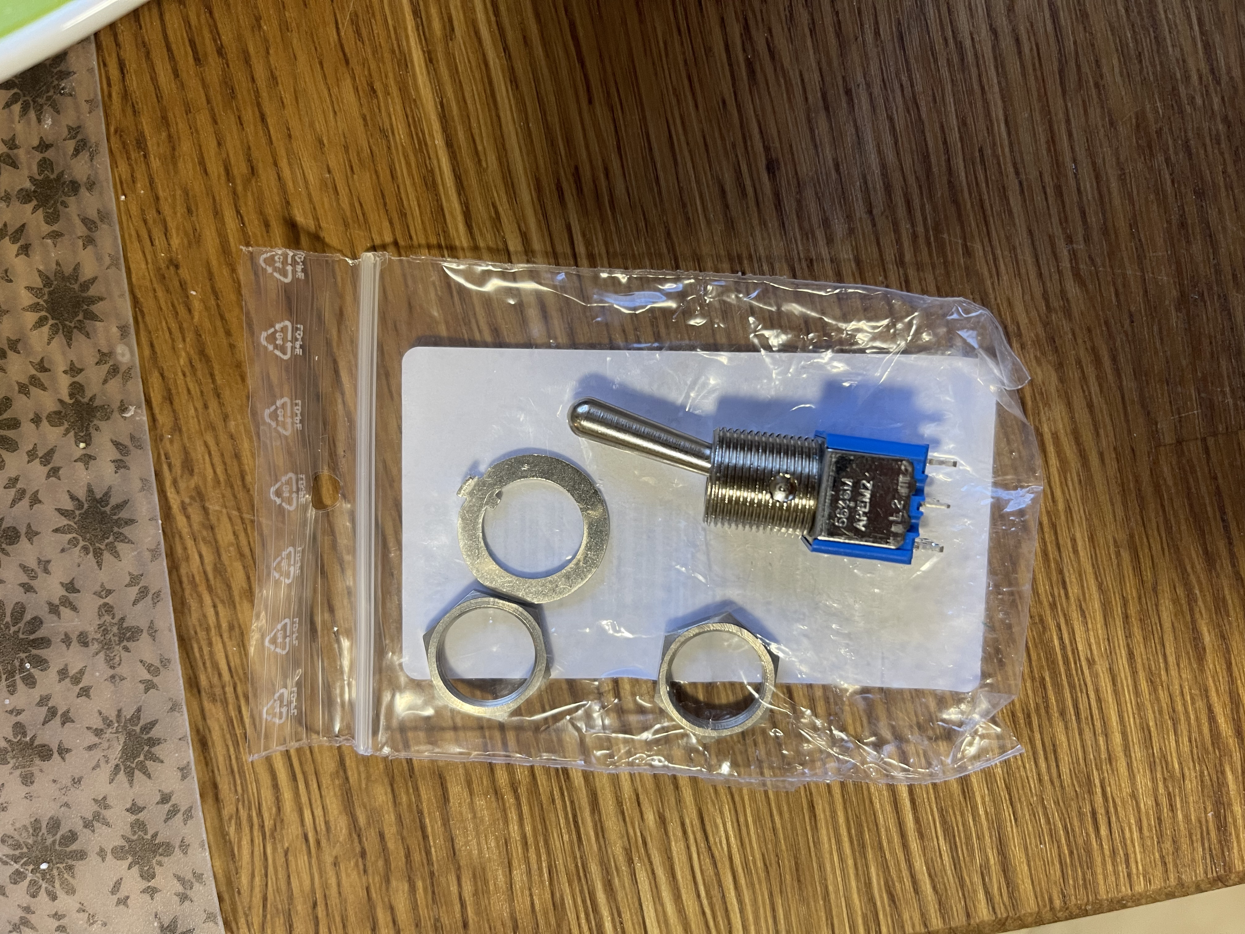
| 7 | link switch | SPST switch of your choice | |||
| 8 | Powerswitch | DPST 12mm diameter | 12euro | ||
| 9 | case part | you need distance spacer 28x 5mm-10mm height M3 for the psu you need 4 x 5mm height spacer M3 | |||
| 10 | case part | 4x M4 screws 15-20mm lenght for the output transformer mounting | |||
| 11 | screws | you need at minimum 28mm flat M3 screws - lenght 6mm to mount the spacer from bottom | |||
| 12 | screws | a lot of M3 screws and washers, nuts for thge pcb mounting and XLR connectors | |||
| 13 | Rotary switches | 2x 4pole 3positions 2x 2Pole 6 positions (change the locker to 5) | lorlin or C&K | ||
| 14 | pcb parts | Solder nails and connectors 1mm diameter for the rotarty switch pcbs and main pcbs | |||
| 15 | cable | powercable 1.5mm2, shielded cable 2 and 3 pole, and few meters 0.5mm2 for interconnection between pcbs | |||
| 16 | headers | I used MTA and molex connections as shown in my pictures | |||
| 17 | jewel lamp | I used from TME: | AE-C027500NAH from tme.eu |
Buildinfos:
Building The DIY 1176LN Revision D.pdf
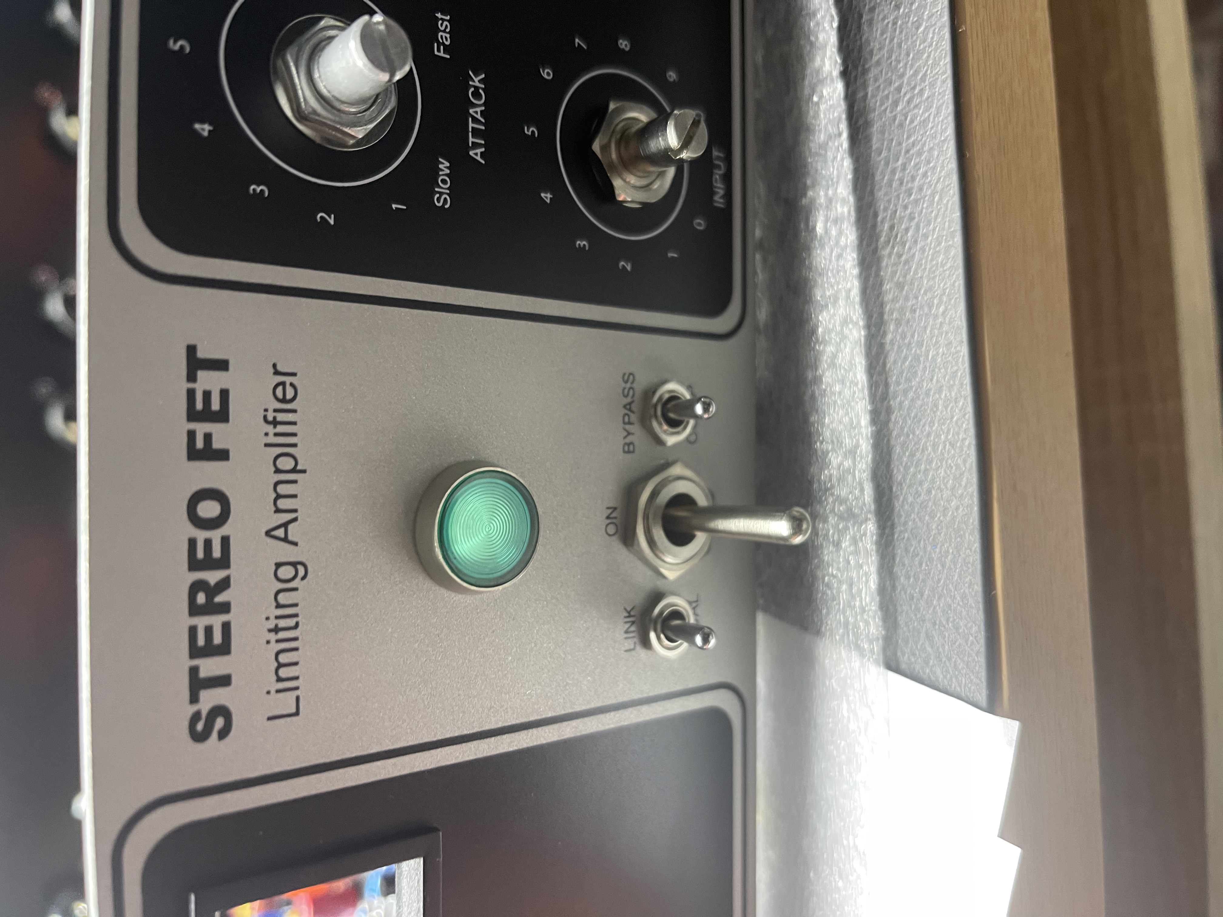
The 1176 doesn't have a true bypass, just a GR off. The GR off is usually placed as a switch on the attack pot.
or use : True Bypass Module – Obsoletetechnology → LED can be powered by a 3PDT switch
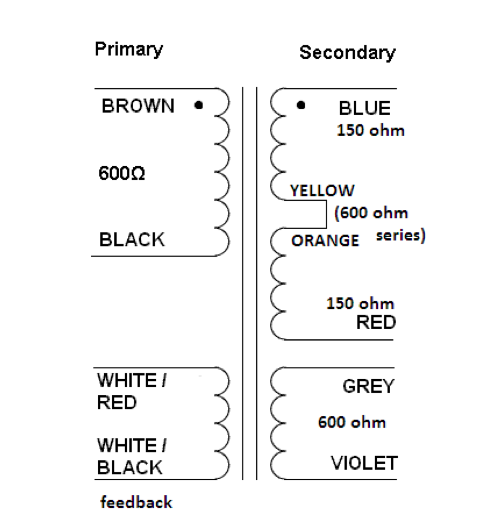
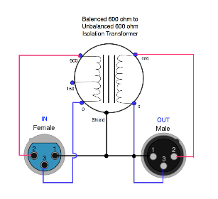
Wiring example
link switch guide
176 manual - HQ - draft edition.pdf
Wiring the 1176LN Clone - Rotary Version.pdf. → for instructions of the wiring - pots and switch
Nmats:
I've included potentiometer assignments too that aren't on the silkscreen layer of the boards: ccw=counter-clockwise - the contact where the wiper comes to rest if the shaft is turned all the way to the left when the pot is viewed from the front; wiper=the middle contact; cw=clockwise - the contact where the wiper comes to rest if the shaft is turned all the way to the right. If you have any doubt, turn the shaft all the way to the end stop and measure the resistance from the middle terminal to each of the other lugs. The one that shows the lowest resistance is the one where the wiper is closest to. It should read very close to zero ohms.