Page History:
| Date | Autor | Change | |
|---|---|---|---|
| 09.May 2018 | LED-man | Initital - Structure | |
| 28.May 2019 | LED-man | BOM added | |
| 30. July 2019 | LED-man | Global content updates | |
Table of Contents
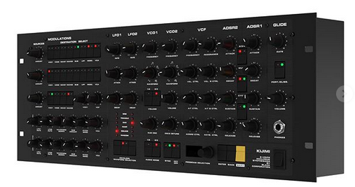
Welcome to the KIJIMI Documentation
"As Synthtopia reports, the Kijimi is inspired by the sound of the RSF Polykobol, a rare French polysynth from the late ’70s that was only available in very limited quantities. According to Instagram posts from Black Corporation, the synth will be available both pre-built and as a DIY kit."
source: http://www.factmag.com/2018/04/03/black-corporation-kijimi-synth/
Product Info:
the KIJIMI Synthesizer is a product of the Black Corparation located in Tokio.
It´s available in 2 different Version:
- DIY Kit contains 12 PCBs (mostly THT) https://www.deckardsdream.com/product/kijimi-kit-preorder-run1 (total costs for the pcbs are: $999)
- Preassambled with Case ready to use https://www.deckardsdream.com/product/kijimi-built-preorder-run1 (total costs: $3749)
The DIY kit consists of 12 PCBs:
- frontpanel board
- motherboard
- 8x voice cards
- power supply board
- connectors board
The motherboard has the MCU and DACs (digital to analogue converters used to control the analogue circuitry) preinstalled, the remaining parts you have to buy yourself from a local supplier. Some DIY shops will provide full parts kits.
Most of the remaining parts are thruhole, except for power filtering ceramic capacitors, which are large (0805 size), all same value (0.1uF) and located on the opposite side of the thruhole parts on the PCB.
The frontpanel and rack case will be supplied by DIY HUB.
BOM:
new BOM from July 2019 with improved Sound, i renamed the File because Roman used the same Filename as before which can confuse and ends in mistakes when you open accidentally an older file with same name.
BOM from 23.July 2019
KIJIMI-BOM-REV1.01_DSLMANxlsx.xlsx
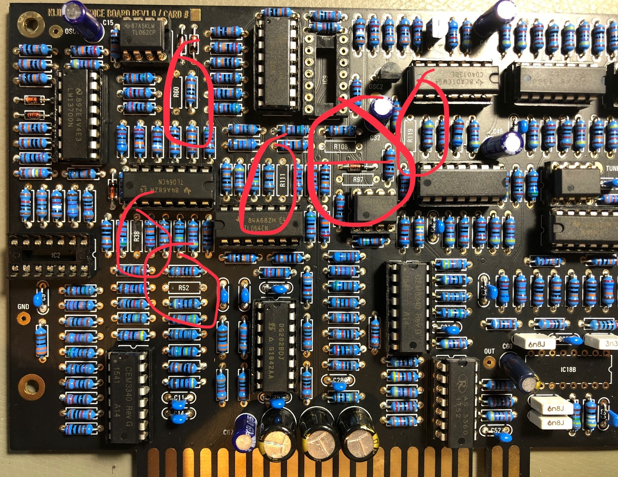
the Difference between first (v1.02) and latest BOM (xxx_DSLmanxlsx.) which improve the sound:
Voicecard:
replace R108 from 10K to 20K
replace R111, R52 from 91K to 20K
replace R38, R97 from 330K to 576K (i used a 560K plus a 20K resistor in series which was measured to 575k (1% resistors)
remove R60 , R119 (220R) → not installed
replace IC2 and IC9 from TL064 to TL074
picture source: Facebook Luther Stevebennett
click to enlarge:

MOUSER Basket: (imported from above xls) (updated 28.May 05:40PM GMT+1) updated see issue list 1.June.2019
https://www.mouser.com/ProjectManager/ProjectDetail.aspx?AccessID=6285be713e
improved for more parts - same price, the quantity is noted as "customer note" on each bag.
Total costs of Material:
600€ plus VAT Mouser (€ incl.19% german VAT)
AS3360 100€
AS3340 80€
ssi2144 ICs (VCF) 55€
OLED 5€
Potentiometer - 35€
Knobs 25€
Noise IC 10€
IC Sockets 20€
XMOS Programmer 22€
metalparts 20€
EDGE card holder 10€
pcb/panel plus VAT 1200€
case: ca.250€
____
TOTAL around: 2530€
Don´t miss the frontpanel and case from DIYHUB http://siddarthianinnovations.bigcartel.com/
please respect your local requirements/laws for a powersupply (110V AC/ 230V AC) and
doublecheck the power input jack polarity (inside +) and
the diameter of 2.1mm or 2.5mm of the plug/jack or you learn it in the hard way ![]()
Display OLED
make sure your OLED folow this pinout VCC-GND-SCL-SDA, very often shows the shop the correct pinout but deliver another type.
AND short the pins on the display side (where the Frontpanel is) to prevent shorts to the Frontpanel.
if you cant source the correct display (pin) use restore legs and bend they - use cable shrink tube to protect this for shorts
Software/Firmware/Bootloader:
Black Corporation Firmware Updater.app.zip (only for updater not for first install)
Kijimi Factory Presets MJ (1.2).syx (presets - transfer it with sysexlib. per KIjimis USB-Midi-interface)
Kijimi1.1.0.bin(only for updater not for first install)
Updater App Instructions:
Kijimi FW Updating instructions.pdf
Installation of the Bootloader for the Kijimi DIY Version:
you need both files: (boot loader and firmware)
Download for (OSX) XMOS TIME COMPOSER and copy it to you Application folder.
Install JAVA 6 from:
https://support.apple.com/kb/DL1572?locale=de_DE
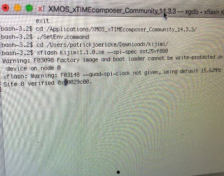
turn the power off , install the xmas programmer in the IDC Socket, connect a USB cable to the xmas programmer, then:
OSX how-to
1. Open terminal
2. Type cd /Applications/XMOS_xTIMEcomposer_Community_14.3.3/
3. Press enter
4. Type ./SetEnv.command
5. Press enter
6. Type cd /Path/to/fw/folder
7. Press enter
8. type xflash Kijimi1.1.0.xe —spi-spec sst25vf080
(power on Kijimi yet)
9. Press enter
10. wait - after 30seconds or one minute your terminal starts with same infos - ignore the first message (Warning: F0398 Factory...) see on bottom the picture.
message, after further seconds the terminal shows you some memory addresses which are written, and then: finished successfully, on the KIJIMI the OLED Display must show you some graphics (PNL mode etc)
Here´s a Video from me about the Firmware Installation:
Calibration
everything is available in the software menu
- Potentiometer Calibration
- set the Voicecard amount to the value what you have installed
- set the Midi Settings to MPE or CP etc. (Channel pressure for standard keyboards)
- calibrate OSC 1 ..2 ..3...
- calibrate VCF
Current identified Errors/Omissions/Errata:
| Date | Location | Identified Issue | Resolution | update |
|---|---|---|---|---|
| May 29, 2018 | BOM hw board | R119, R120, R121 not in BOm 1.02 | R119 4K7 R120 100R R121 2K2 | BOM project updated-1June2019 |
| May2019 | OLED DISPLAY | Double check the OLED pinout | rin case of wrong pinout - remove 2 oled pinheader puns and use a resistor leg and cable tube shrink | |
| BAT43 x2 missing D3 D4 on Harware board | BOM project updated-1June2019 | |||
| 12 Jun2019 | BOM hw board | C34 missing in BOM | 560pf mlcc RM5 | |
| 30 July 2019 | Controlboard | dont install a Metal spacer between controlboard and mainboard in the middle of the pcb - otherwise it touch the card slot adapter pins
| use only the short 7mm spacer and a screw/nut from rear. | |
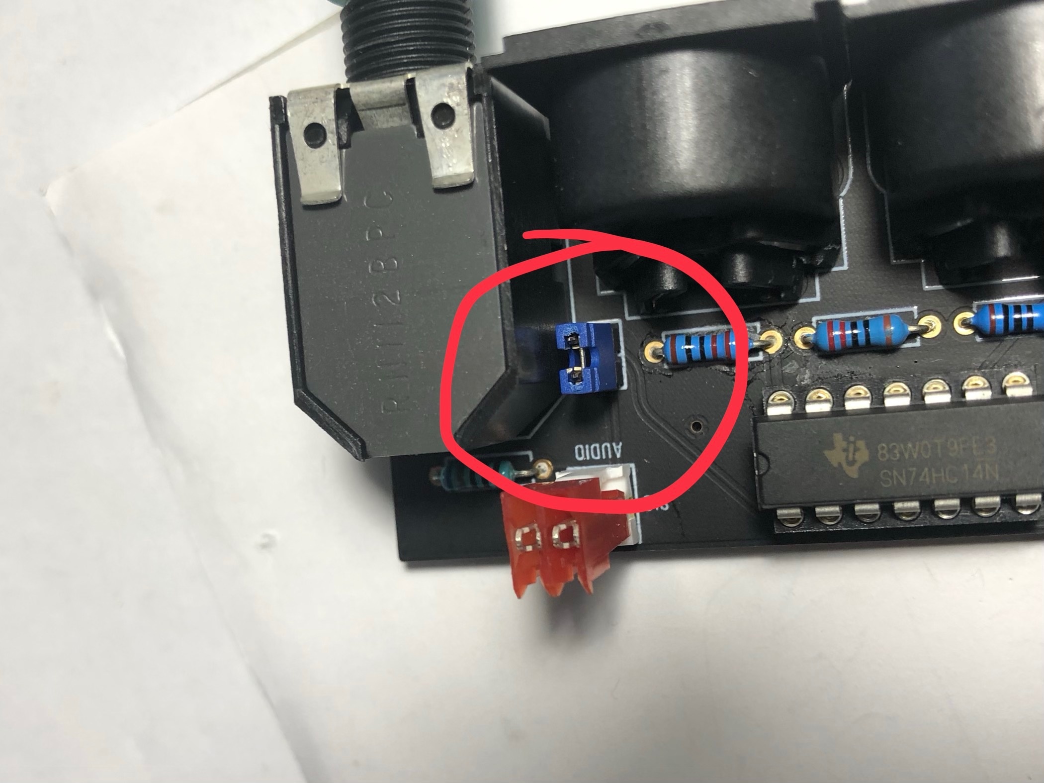
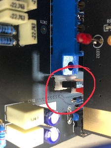
| 30 July | Audio output | install on both locations a jumper (bridge both pins) if you use the flat ribbon cable. when you use the MTA100 headers with coax cable, dont install the jumpers. |
| |
| 30 July 2019 | info | use a 24V Center positive Powersupply | don't use the 12V PSU from DDRM DIY Version. |
Wooden Case (same as in DDRM project)
Ross Lammond (UK) http://www.lamonddesign.co.uk/index/
please note, the case can ordered in different HE, order 5HE to include a effect device or expander (an expander isn´t confirmed yet)
Gallery |
|---|
| There are no images attached to this page. |
Featured Pages
Content by label
There is no content with the specified labels