I reworked a PSU design, because the most bipolar psu pcbs doesn't match with my requirements.
This Psu is great in combination with an Yamaha PA-30, perfect for the TTSH - no EMV problems or hum from the switching DC solution and no hum on the reverb.
The Yamaha PA-30 gives you around 700mA on 15V and 700mA on -15V.
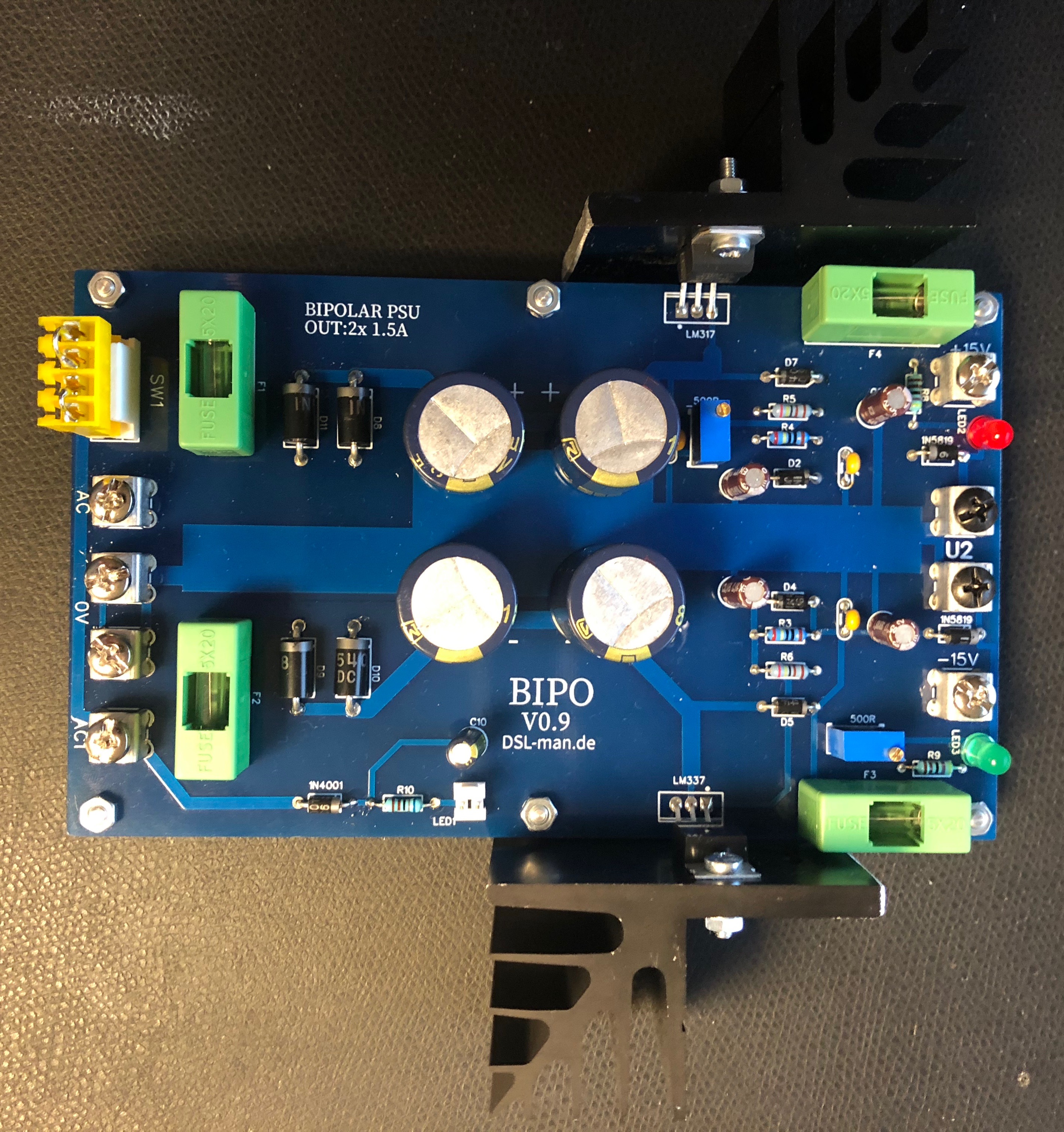
Inputs and Outputs are mechanical very stable and the pcb can be attached by 6 Screws.
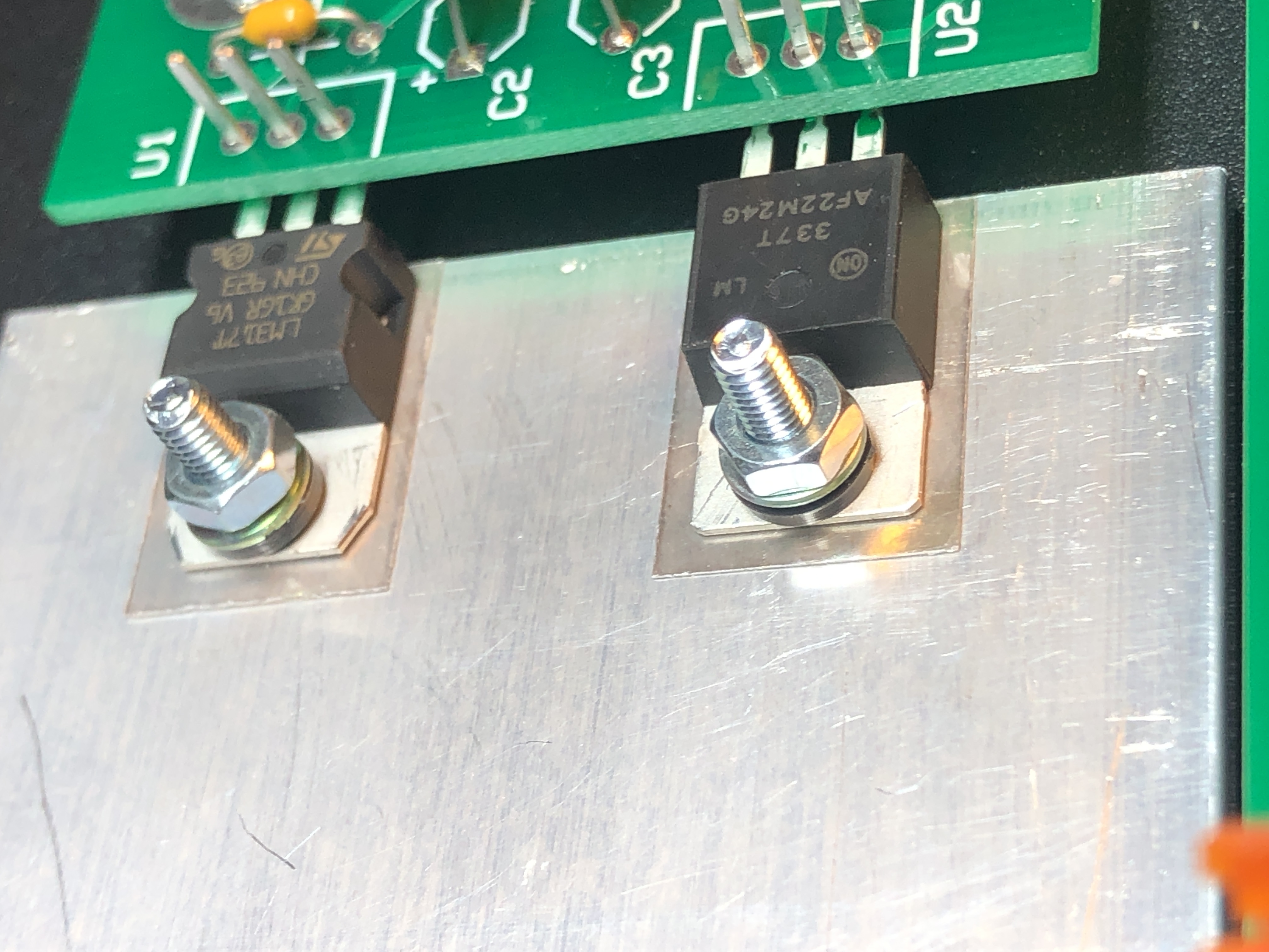
The Voltage regulators can be mount directly (with isolation/glimmer pads) on a metal case like the TTSH or with cooling frames.
you can use MTA100 headers instead of the LEDs - to connect 1 or 2 external Led holder in your device.
Its important to double check every rectifier/diode and capacitor and your wiring before you test the circuit.
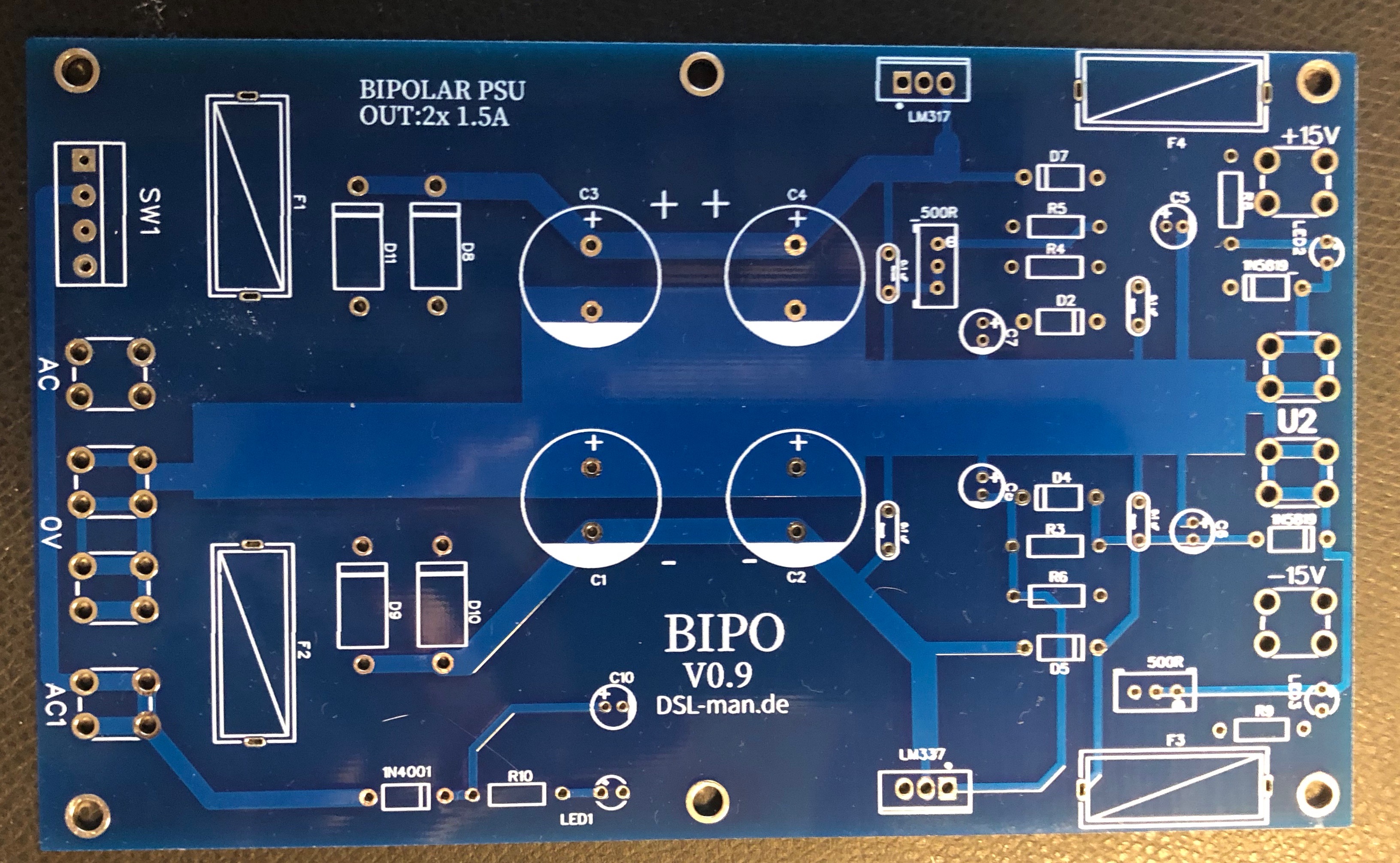
BOM: (09.Aug.2020)
BOM_PSU_rev1.1_2020-08-09_17-15-03.xls
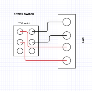
for SW1: don't use the MTA header
Build:
just install all parts from the BOM. use Glimmer(isolation) in case you attach both regulators to the same metal/cooler
for the switch SW1 - don't use a header - connect directly cables to SW1.
use the trimmer to get the correct voltage
wiring for Sw1:
Fuse sizing:
use at the input fuses (F1/F2) the value which your AC-AC transformer offer - for the Yamaha PA.30 its max. 750mA (500mA/630mA should be fine)
for the secondary fuse use a value which is 10-20% bigger than what your device ask (for example a TTSH works great with 2x 500mA fuses and should be work with a 320mA too (depends on the additional mods)
Schematic:
Schematic_PSU_rev0.9_2020-11-02_19-11-13.pdf
Example for TTSH installation:
the case of the TTSH is used as a cooling block

Heres´an example of an isolated Installation with Glimmer and plastic rings - its important that both voltage regulators are isolated - there's also a plastic inlet on bottom of the nut which isolated the screw from the voltage regulator body.