| Panel | ||||||||||
|---|---|---|---|---|---|---|---|---|---|---|
| ||||||||||
Projecttitel: Juergen Haible Tau Pipe PhaserStatus:
Startdate: Juni 2014Duedate: Juni 2014Manufacture link: http://www.jhaible.info/tau/jh_tau.html |
for Randomsource Version check my subpage:
| Children Display |
|---|
Fullkit build from bridechamber in MOTM Format with CA3046
i have changed all cheap lowcost ceramic to MLCC capaciators and used IC-socks.
BOM
Component Overlay
jh_tau_component_overlay_with_comments.pdf
Important update: (from J.H)
I noticed that the 100nF 0805 SMD bypass capacitors that I've soldered into my prototype are only rated for 25V.
What you need, by any means, are 35V (or higher) rated capacitors.
While ordering new caps from Reichelt, I noticed that for 0805 parts, the 100nF come in 25V, but the 47nF are rated 63V.
So I ordered a bunch of 47nF/63V 0805 caps for future use in my electronics lab.
Bottom line for you:
If you can actually get 0805 parts 100nF with 35V or more, it's fine to use these.
If not, go for 47nF with 35V or more.
...
pin1 = -15V (trace goes to diode)
MOTM standard: ![]() approved by DSL-man
approved by DSL-man
...
2= Ground
3= Ground
4= -15V
use a diodetester and check for shorts..between all pins.. further you can check that the ground goes to left headers like led etc.
...
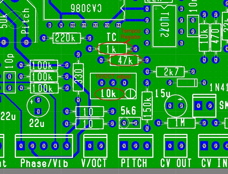
Tempco Resistors
My version of the 20-pole-Phaser was designed with a 560 Ohm Tempco Resistor for Temperature compensation of the 1V/Octave tracking.
(The Tau "Pipe" Phaser used a 1.87 kOhm Tempco Resistor.)
You can use a 1 kOhm Tempco Resistor, which is a much more common value, if you also change two other component values.
This picture shows what you have to change. (Or click on image to enlarge.)
Calibration
1. Pitch trimmer setting. (I guess No input signal is needed to do this, or Yes?)
First set:
a. The external “Pitch” pot to middle position (?)
...
Then adjust the pitch trimmer for the most pleasant sweep sound.
2. Resonance trimmer setting. (Is an input signal necessary and if yes, any suggested frequency?)
First set:
a. The “Resonance” trimmer to maximum (cw).
...
c. The nice/screaming oscillation “switch” (if installed), to the “off” (nice) position.
Then reduce “Resonance” trimmer until you like it
Frontpanel connections:
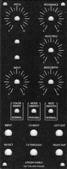
Pots:
Pitch Knob (Manual Sweep) 100k Linear - to "pitch" on PCB
...