...
- lets start with the powersupply board - add all needed parts on the pcb, start with the two SMT power regulators.
there is one missing part (a dual choke) - please use wire links here or resistor legs
turn the 2 pol MTA header as described in the picture
if needed - wash the pcb carfully on the solderside
testing/trimming: use a 18-24V DC powersupply for input and set the output to 15V/-15V by usage of the both trimmers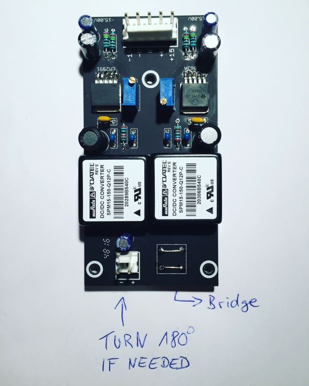
- Mainboard PCB - place all IC-Sockets ( tin one ic socket from top, place the ic socket and heat the ic socket pin - the socket drop in place
best practise - begin with the "most use values" and end with the value range Mainboard PCB - start with 100K resistors, 10K, 1K, 1M, 100R (reverb), 10R (Amp) 10M (top right)
if done - 47k, 4k7, 470K, 4M7, – 22K, 220K, 220R, 2M2, 33K, 3M3, 330K... — 30K1, 680R, 68K, 68K1, 680K... ..... and all other
please remember: on solderside are few resistors too - on VCO 4027 boards and filter boards too - its your choice to leave it for later or assembly it yet too (i prefer later) - Mainboard PCB - place all rectifiers 1N4148
- solder from top all parts
- cut the resistor and rectifier legs from bottom side
- place all MLCC caps and solder from top
- place all polyester/polypropylen caps - bend the legs from top
- add all transistors in place and solder one pin from top -(except the 2N3954, both 2N3958 - if you cant test this, use a milled IC-socket and cut the pins out - use this as socket)
- turn the pcb and solder all pins. (no switches, no fader, no jacks, no pot, no trimmers)
- you find on solderside few resistors
- wash the pcb 2-3 times if needed, i use Ispopropylen alcohole
- make a break yet - the pcb needs time to dry - if you dont need a break - assembly the filterboards and 3 VCO 4027 boards - wash them too, make sure you use flat 10uF electrolyt capacitors, use c0g, polypropylen or silvamica for the 680pF cap, dont mount the connectionsheaders yet
- Mainboard pcb: its time to add all other parts on the pcb - i prefer multiturn trimmers for the VCO V/oct trimmers 20K or 25K, but remember this can´t mounted on the frontpanel pcb side due to sizing, you have to open your TTSH for trimming the VCO
begin with