| Panel | ||||||||||
|---|---|---|---|---|---|---|---|---|---|---|
| ||||||||||
Projecttitel: Arp1601 CloneStatus:
Startdate: end of 2014Duedate: Summer 2015last update: 08/2020 rev.6B infosthe Name and logo "ARP" is under license by Korg, this pages are for private usage only. Its not allowed to sell your 1601 Sequencer with the brand or logo of "Arp1601" |
pay attention to your PCB Version.
the latest Version is rev.6b (available from Synthcube), which is different from rev.5
(DC-DC adaptor on rev.6A is the same as in rev.1-5)
(DC-DC Adaptor on rev.6B is a Meanwell 6Watt Version)
you find the BOMs on the left side navigation/subpages
| Attachments | ||
|---|---|---|
|
| Gallery | ||||||||
|---|---|---|---|---|---|---|---|---|
|
Buildeguide for rev.5 which is mostly the same like rev.6b (except the PSU, SMT resistor network)
old rev.1-4 in left navigation or here: Buildguide rev.1-4, there are a lot of documents in this older buildguide version
PCB Designator/Component Numbers
ARP 1601 Sequencer Rev 4 - PCB (full).pdf
the most important change to earlier versions:
Changed:
2x LM3046M SMT instead of CA3086 THT (rare part)
1x MC14528 SMT instead of rare THT Version
All Slider Switches changed to other versions.
Panel holes for 3.5mm jacks bigger
lets start:
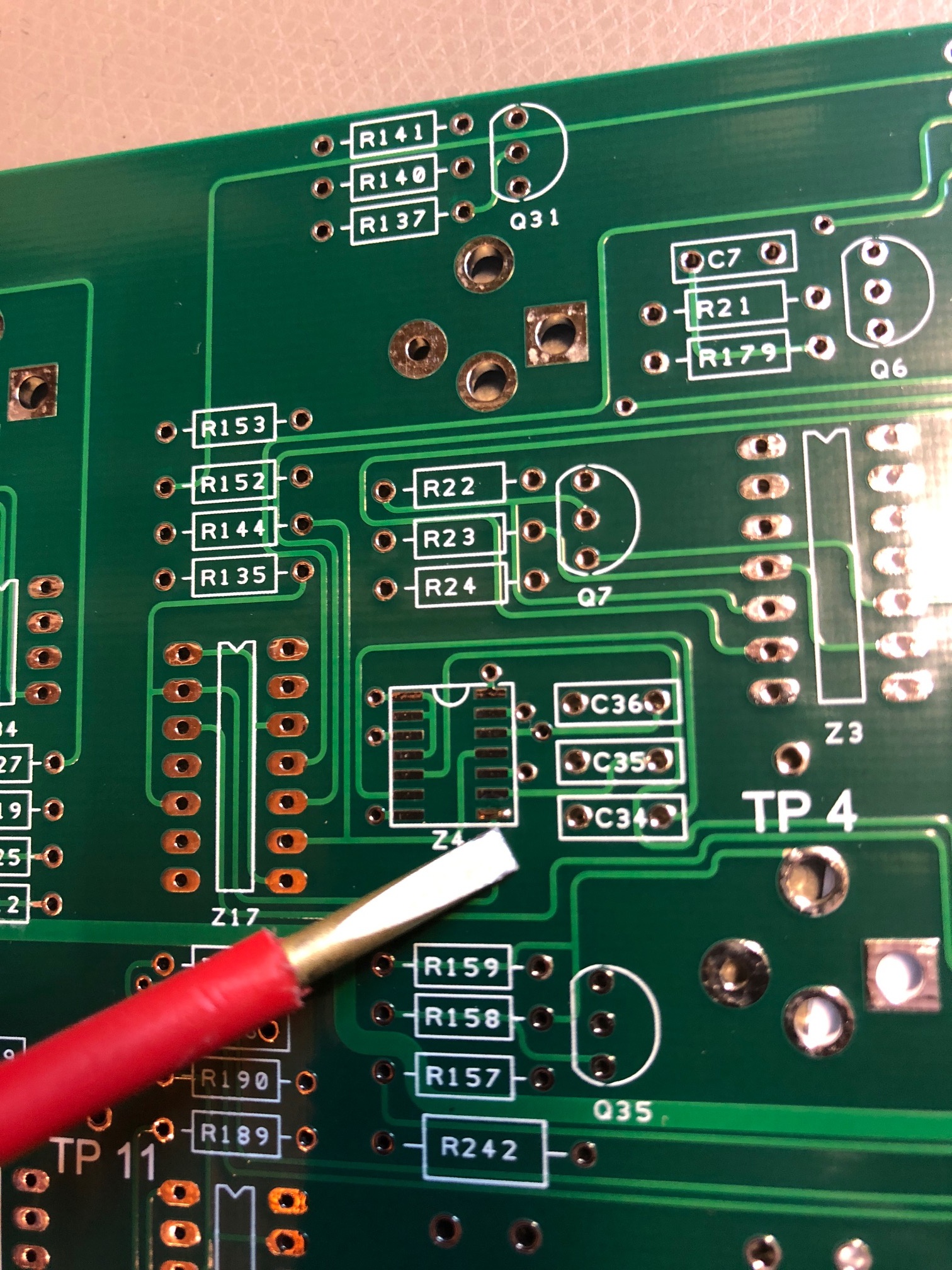
we start with the SMT Parts:
use 0.3mm or 0.5mm soldercore with lead and a small soldertip, add a small solderpoint at one solderpad on pcb.
doublecheck the IC orientation - check my picture for details.
touch with the solder iron the pad where you added before the soldercore, now is your IC fixed, check the correct allignment between the IC pins to the pads.
solder at the outer pins at beginning followed by the other side, dont give the too much heat, good tutorials are at youtube for SMT soldering or ask me to assist you.
second step, Powersupply
what you need to know:
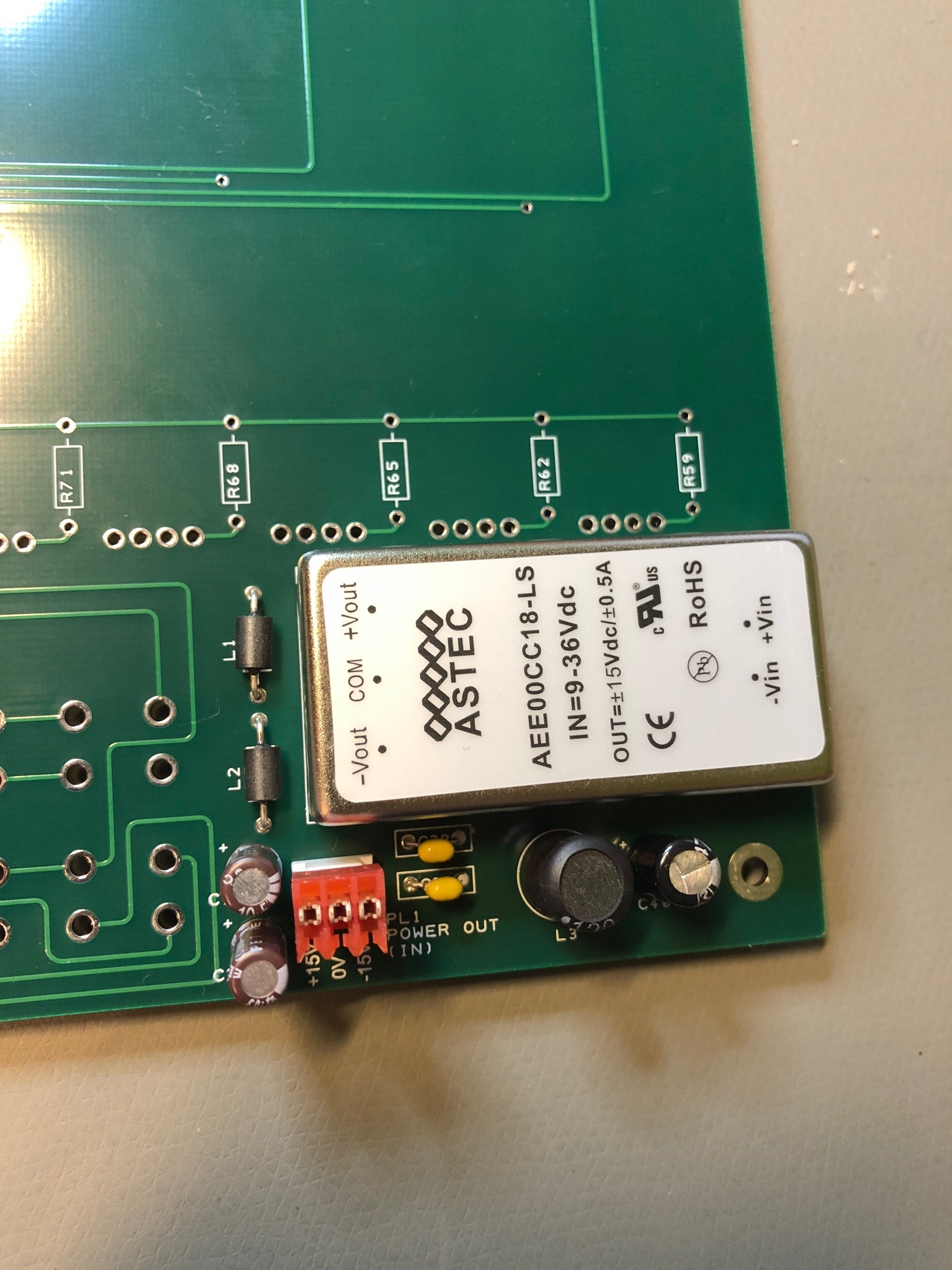
you can power the Sequencer without the internal PSU, if you have a Arp2600 or TTSH, you can use the -15V/15V for the sequencer too, thats why you find a power input (3pin MTA100 close to the DC-DC part) (PL1 on PCB)
internal power:
place and solder (with a big soldertip) the DC-DC adapter on the PCB, solder one middle pin and check the correct placement, sometimes its not close enough on the pcb.
add the L3 (12uH inductor), L1&L2 are ferrite beads., place and solder the 47uF, 2x10uF capacitor and 2x 100nF ceramic disc cap, feel free to add the 3 pin MTA100 header for external input(output)
add the 2 big MTA156 2 pin header on pcb (on left side) thats for the powerswitch and one for the 12V DC-36V DC Power input (PL1)
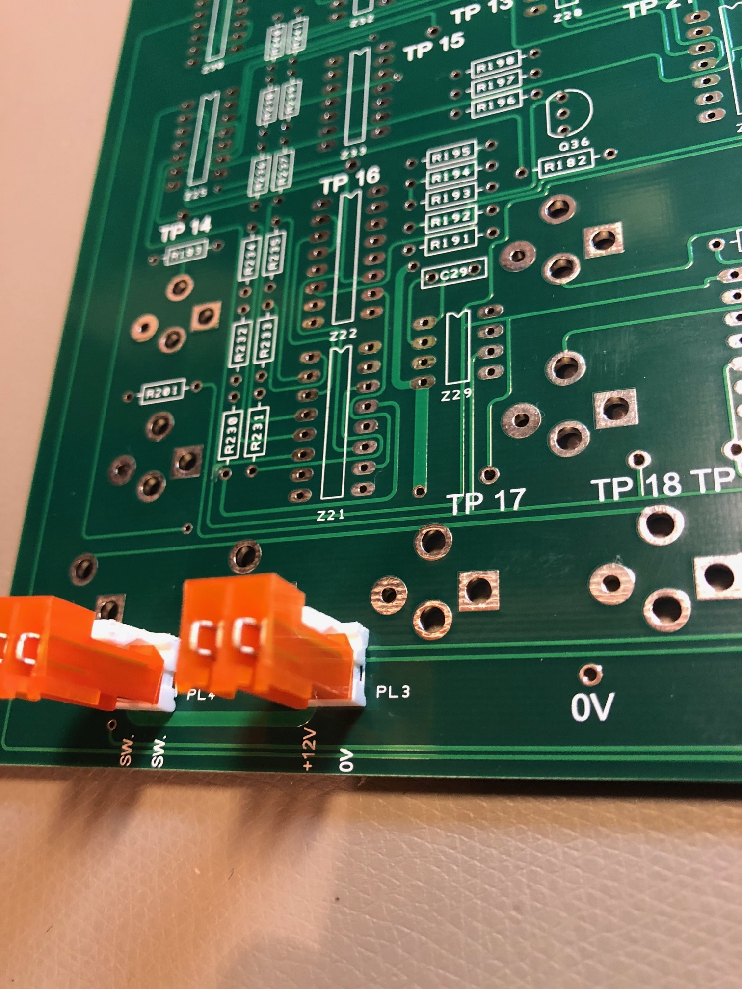
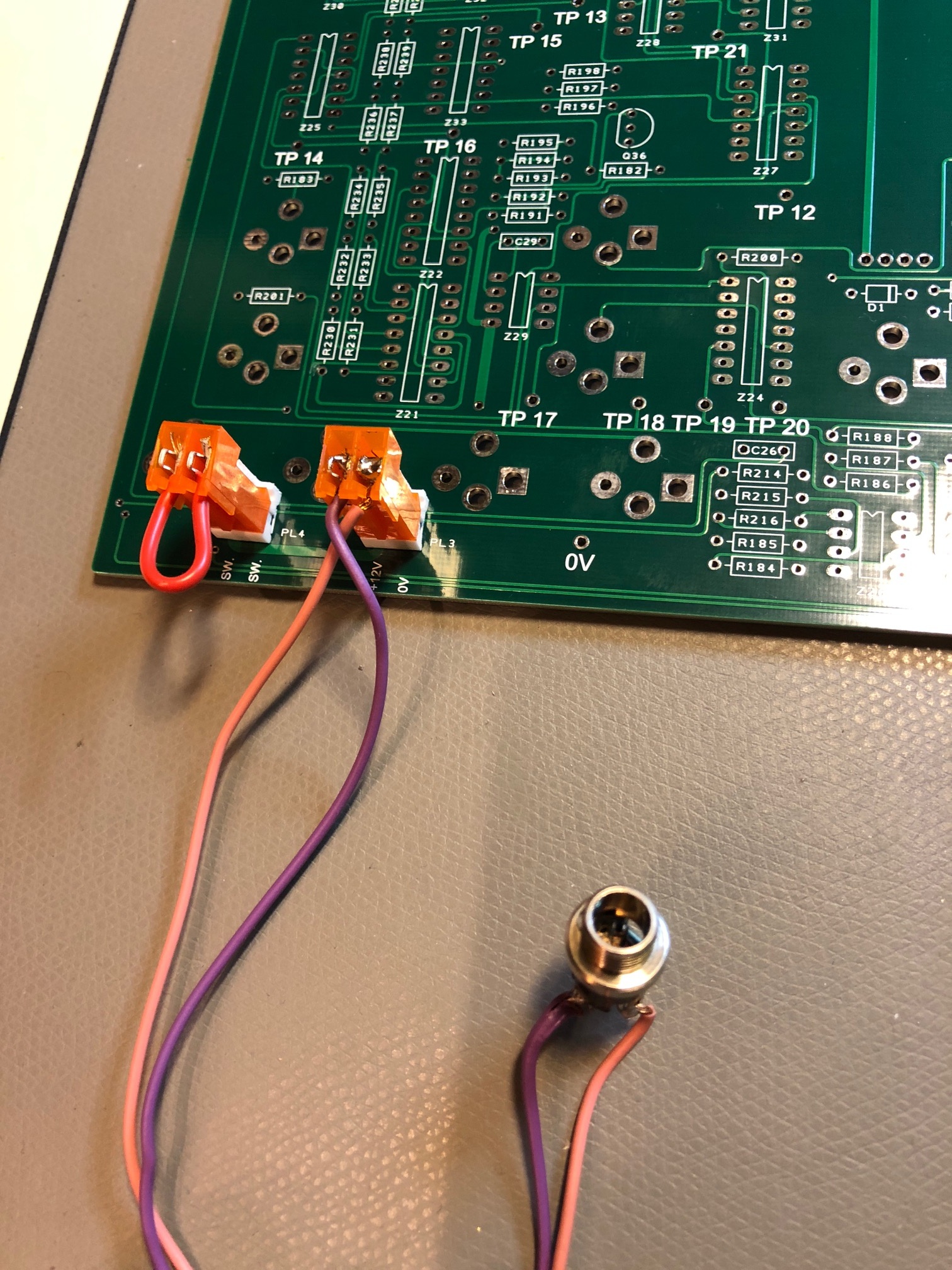
for testing you can bridge the PL4 header (switchheader),
solder all powersupply parts and cut the "part legs/pins " short.
now you can test the powersupply for correct output, it must be measured at the MTA100 power input header (PL1) -15V/15V
only if this voltage is correct, build further steps (around +/- 14.8-15.2V)
Step 3:
Add few spacer on the pcb to have a distance between the desk and pcb
start with the 0.1% resistors..
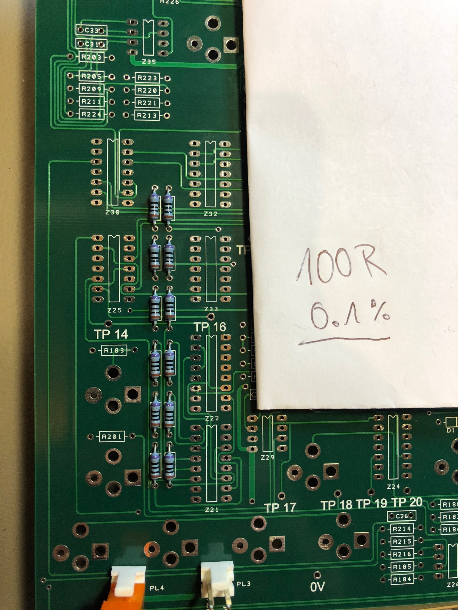
followed by fat 650R/680R/750R resistors (LED DRIVER Resistors)
then: 1K,10K,100K, 22K
followed by all other values, solder from top side one pin, turn the pcb and solder from solderside (thats what i prefer)
Step 4:
add all capacitors and Transistors and solder ..
Step 5: IC sockets and more
add all IC sockets on same pcb side like the resistors, ignore the silkscreen notice about sockets (that means the 6.3mm jacks)
place and solder the 2pin MTA100 (PL2 ) thats the external footswitch input,
remove all spacer and mount the 11mm spacer on the solderside of the pcb.
Step 6: Sliders
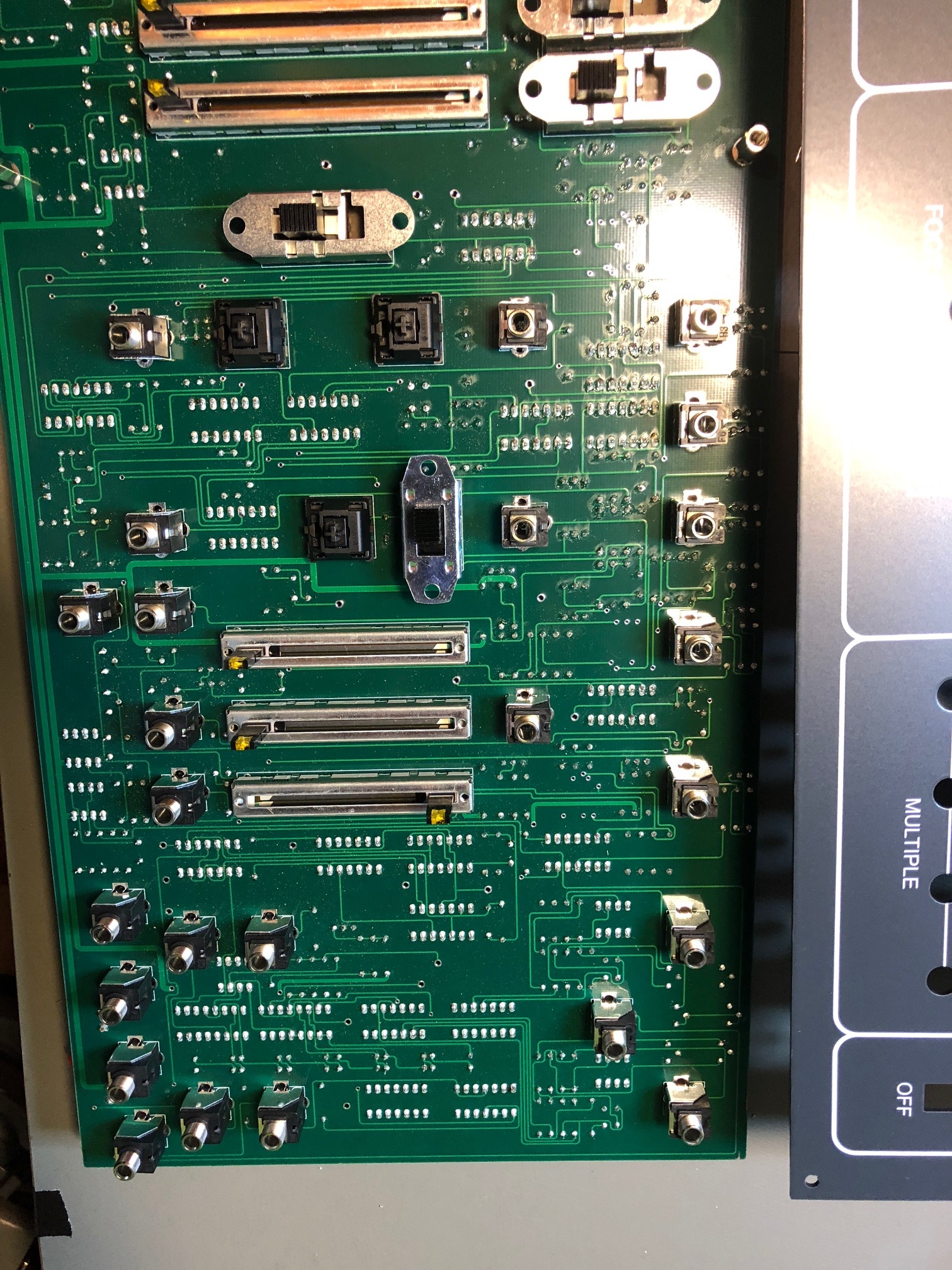
Place the Slider on opposite side of the resistors (you see it on my pictures),
bend few pins to give the slider a temporarily position.
about the 3x 45mm sliders: the FM slider (R14) in the middle is 100K log. (ignore the google doc BOM)
Step 7: jacks
add 2 jacks at the outer positions in place and solder one pin, that helps us later to fix the frontpanel here, because there's no spacer on this side.
only 2 jacks yet.. more on step 9 later
Step 8: Switches
add all switches and the 3 cherry pushbutton switches, solder only the middlepin on the switches temporarily !
Step 9: more jacks
add all other jacks in the position, DONT solder it yet.
Step 10: Frontpanel & more
mount the frontpanel, use the 2 jacks to give the panel on the right side a temporarily fix.
now you must carefully check the alignment, hight, positions of all sliders, jacks, switches.
my best practice tip: solder not so much yet, only 1-2 pins per switch than check again the alignment by using of the switch.
Step 11: IC´s
turn the sequencer on a clean flat desk/table and insert all ICs, double check the orientation.
Step 12: first test
before that: use a jumper at the 2pin MTA100 (PL2 ) thats the external foot switch input, or the sequencer wont start.
move the Switch to trigger, move the clock speed slider to 10-30%, the FM and PW slider to zero.
turn on the sequencer, the STEP LEDS must be move from step to step . clock LED blinks (if not move the slider) and the FM/PWM slider must be illuminated all the time.
IF NOT, power off the machine, remove power, check IC orientation
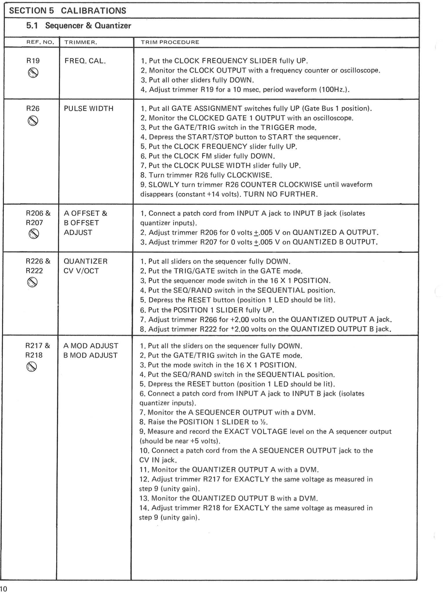
Step 13: Calibration
use the original ARP1601 service manual for it.
Step 14: finishing it up
about the Footswitch, if you dont need the footswitch: use a PC jumper for the PL2 (same as Step12) or connect a switched stereo 6.3mm jack, the TIP is the signal, ground must be normalized to switch pin - when you dont have a 6.3mm plug inside, the tip must be flow to ground.
mount the frontpanel in the boat, the boat is not in the correct allignment - because the metalboat was bend by machine and the metal bounce more or less after this process in different way, that was happen on all metalboats over the last years.
→>> not
OLD rev.2 buildguide only for reference - thats not the actual guide, but it helps you in case of failure
|
NOT APPROVED for REV.5 version !
Schematics from rev.1, not compared to rev.5 ! but its 99.9% the same inside.
ARP 1601 Sequencer - Schematic (round 1).pdf
Panel:
|