| Panel | ||||||||||
|---|---|---|---|---|---|---|---|---|---|---|
| ||||||||||
Projecttitel: Antonus 2600Status:
Startdate: 06/2022Duedate: 03/2023Manufacture link:tbahttps://antonus-synths.com/2600-original-size/Modwiggler : https://www.modwiggler.com/forum/viewtopic.php?t=275887&hilit=antonus |
Page change history
| Expand | ||||
|---|---|---|---|---|
|


BOM:
BOM/schematics/fixes:
A2600FS-BOM-v1.2-buildlog.xlsx was valid for my own build. customers have to follow this:
http://www.antonus-synths.com/antonus2600/antonus%202600%20DIY%20version.zip
this folder is up to date on 25.Jan.2024. and contains:
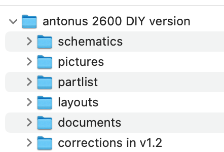
MIDI guide:
Manual MIDI 2600 DUO ENGLISH.pdfMouser Project (doesn't include all parts)
rare Parts sources:
diysynth.de
antonus
ebay
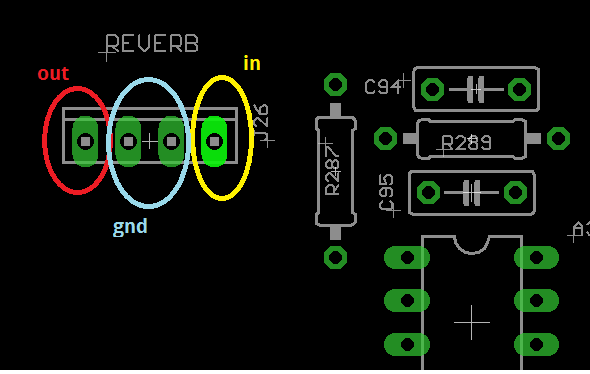
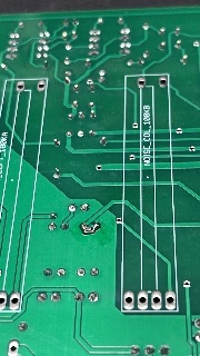
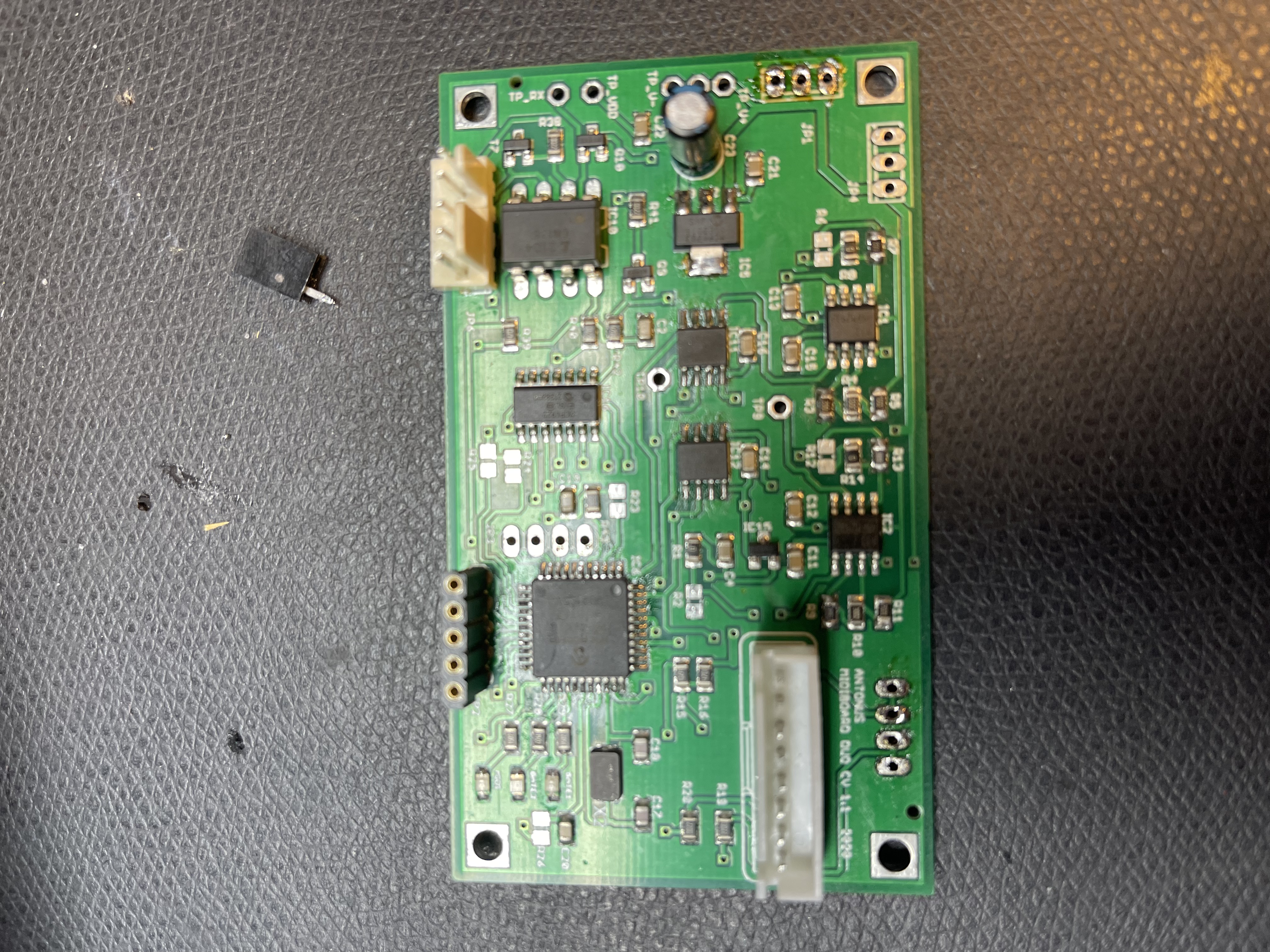
PCB Pictures for Troubleshooting:
Reverb Wiring
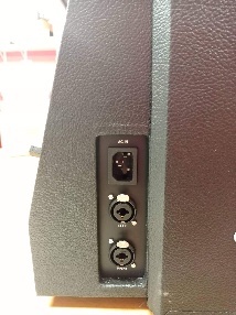
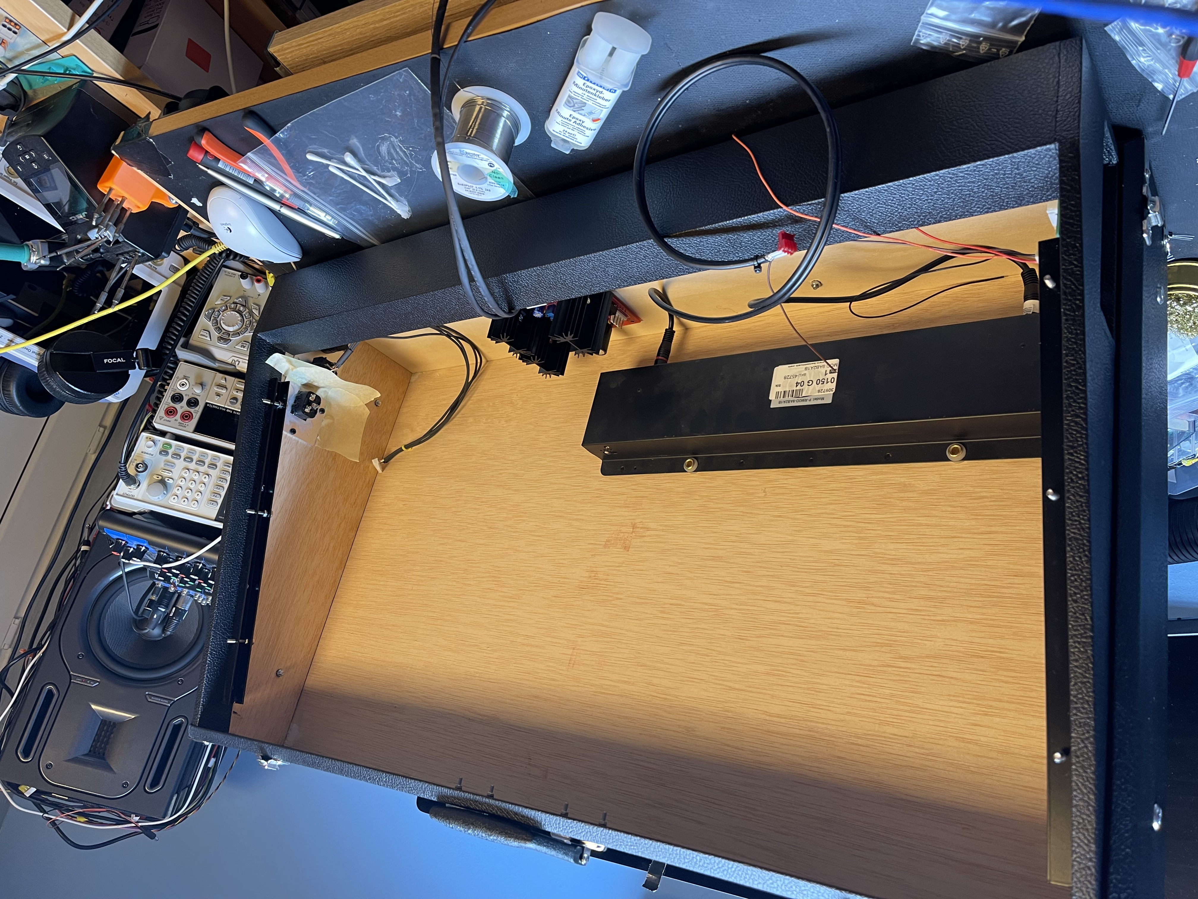
PSU
Speaker connector:
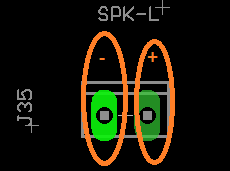
important the Amp needs 16V minimum

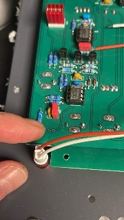
Balance out:


10k added here (bugfix in rev 1.0)

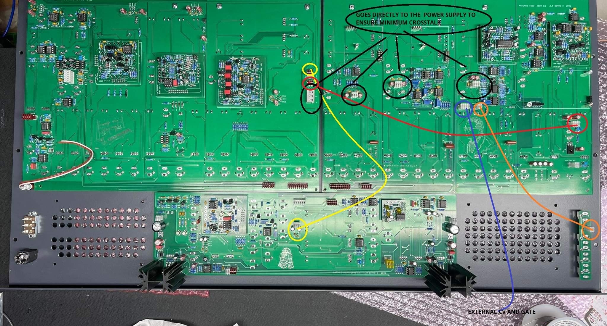
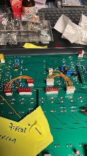
PCB to PCB connection:

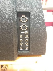
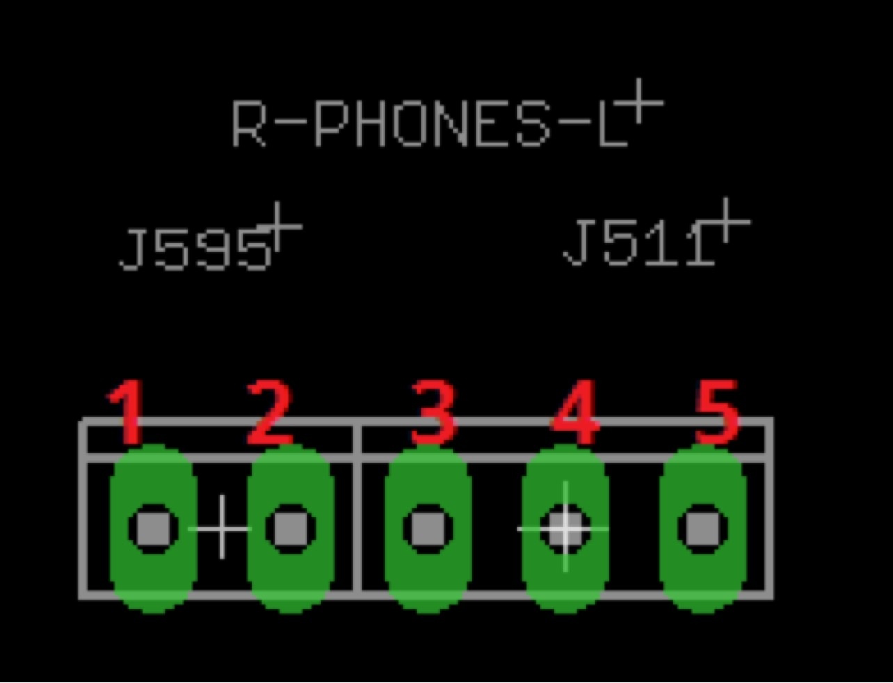
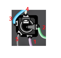
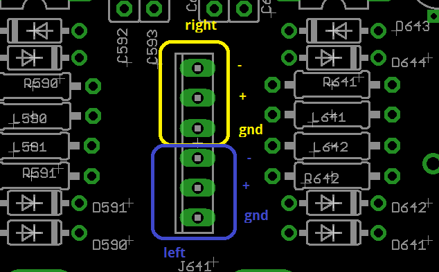
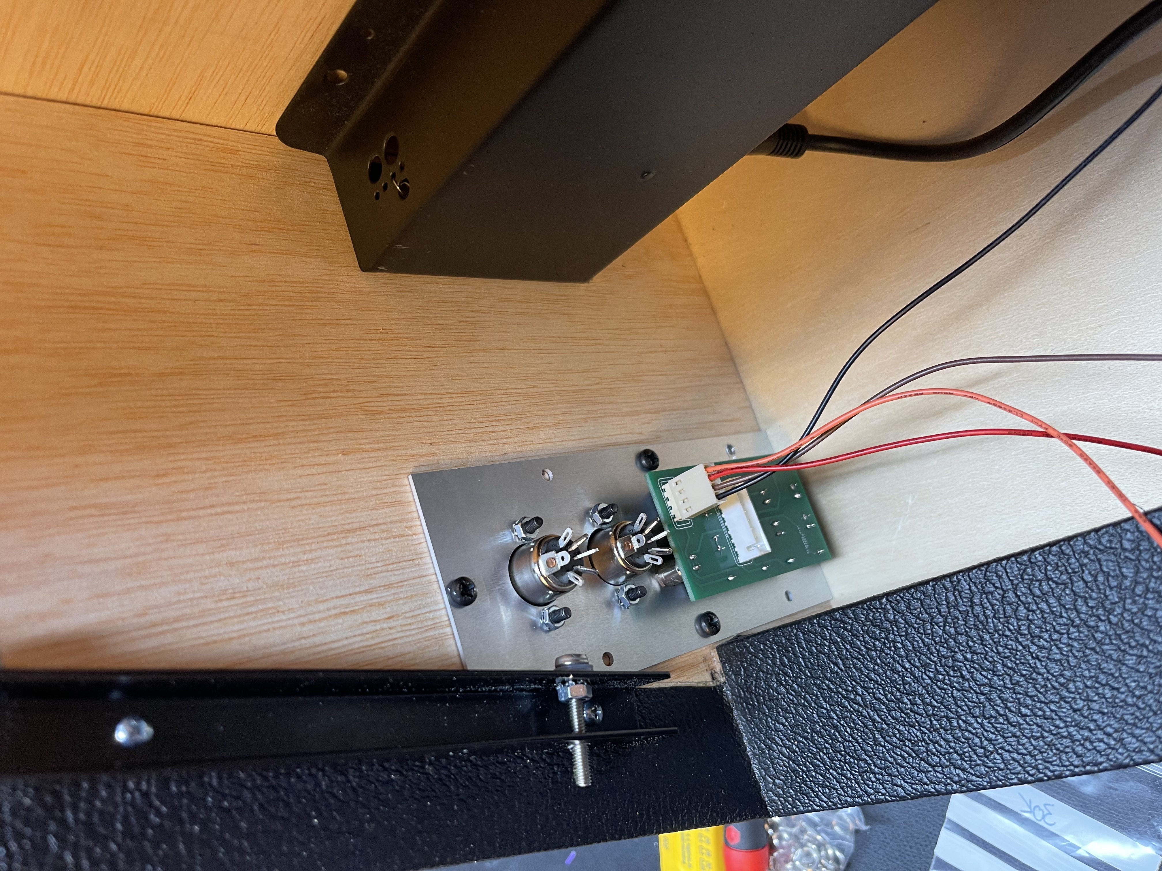
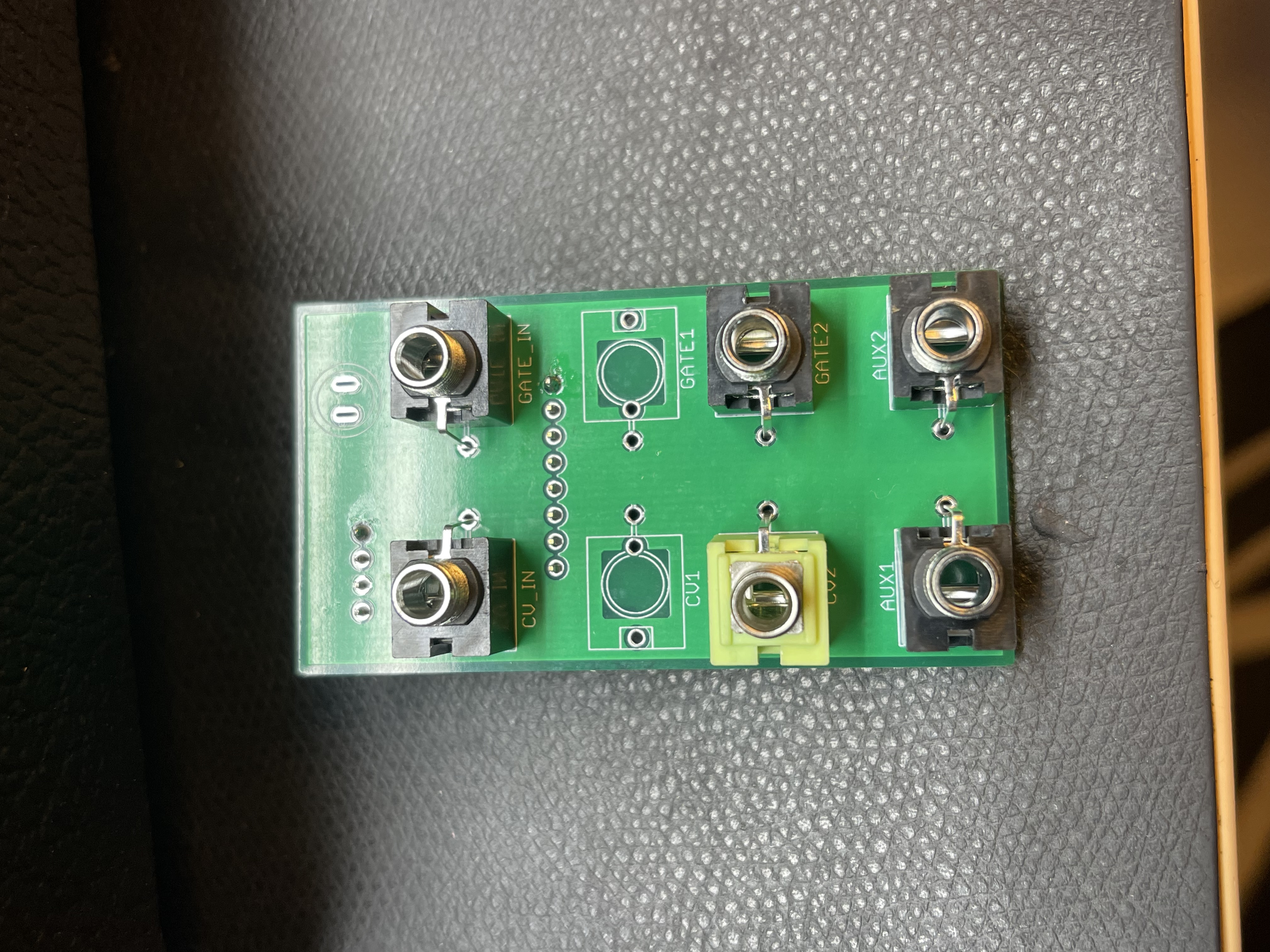
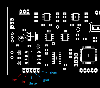
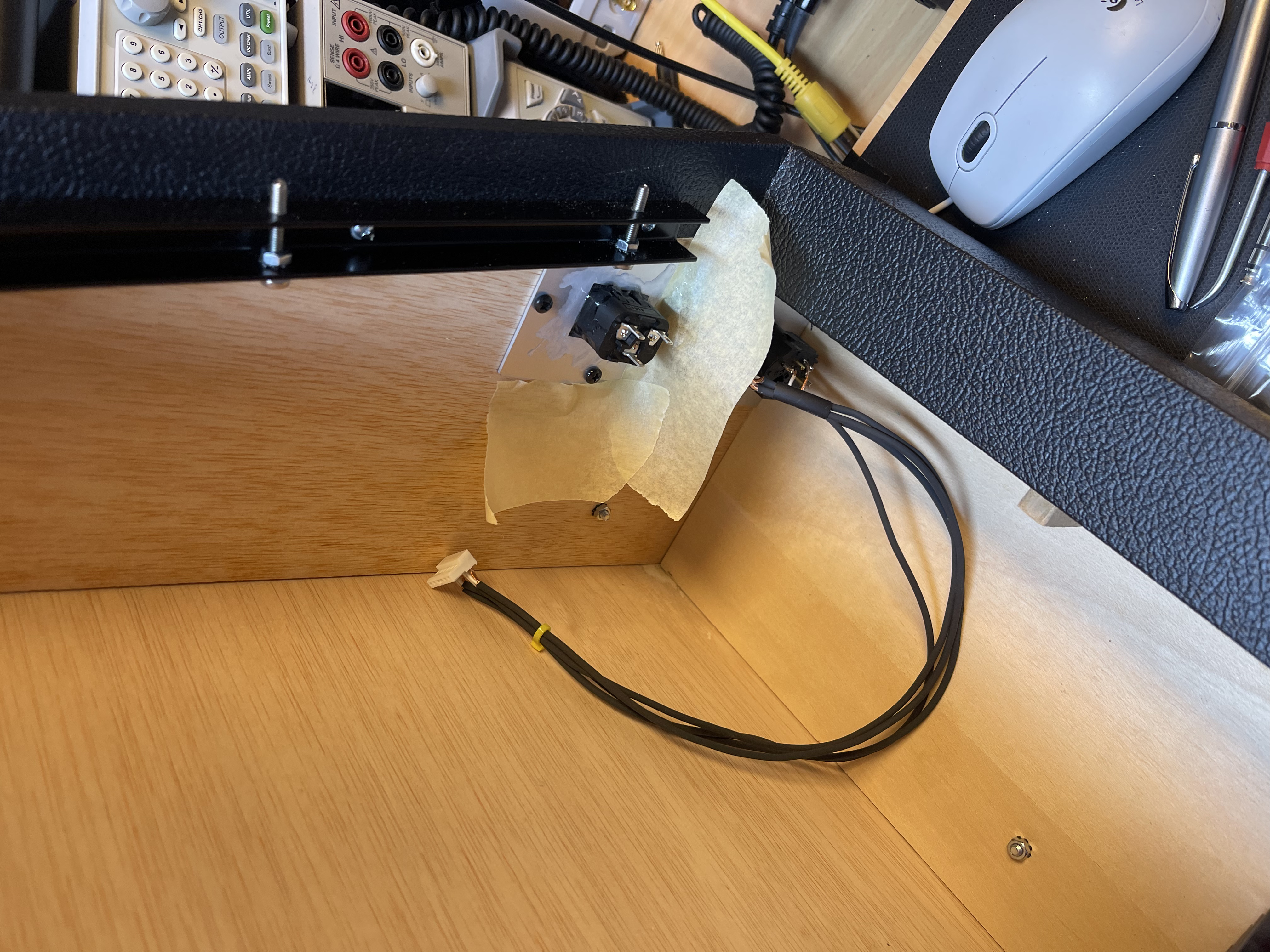
MIDI/CV IO wiring:
please note: the green jack is a stereo jack !!!


e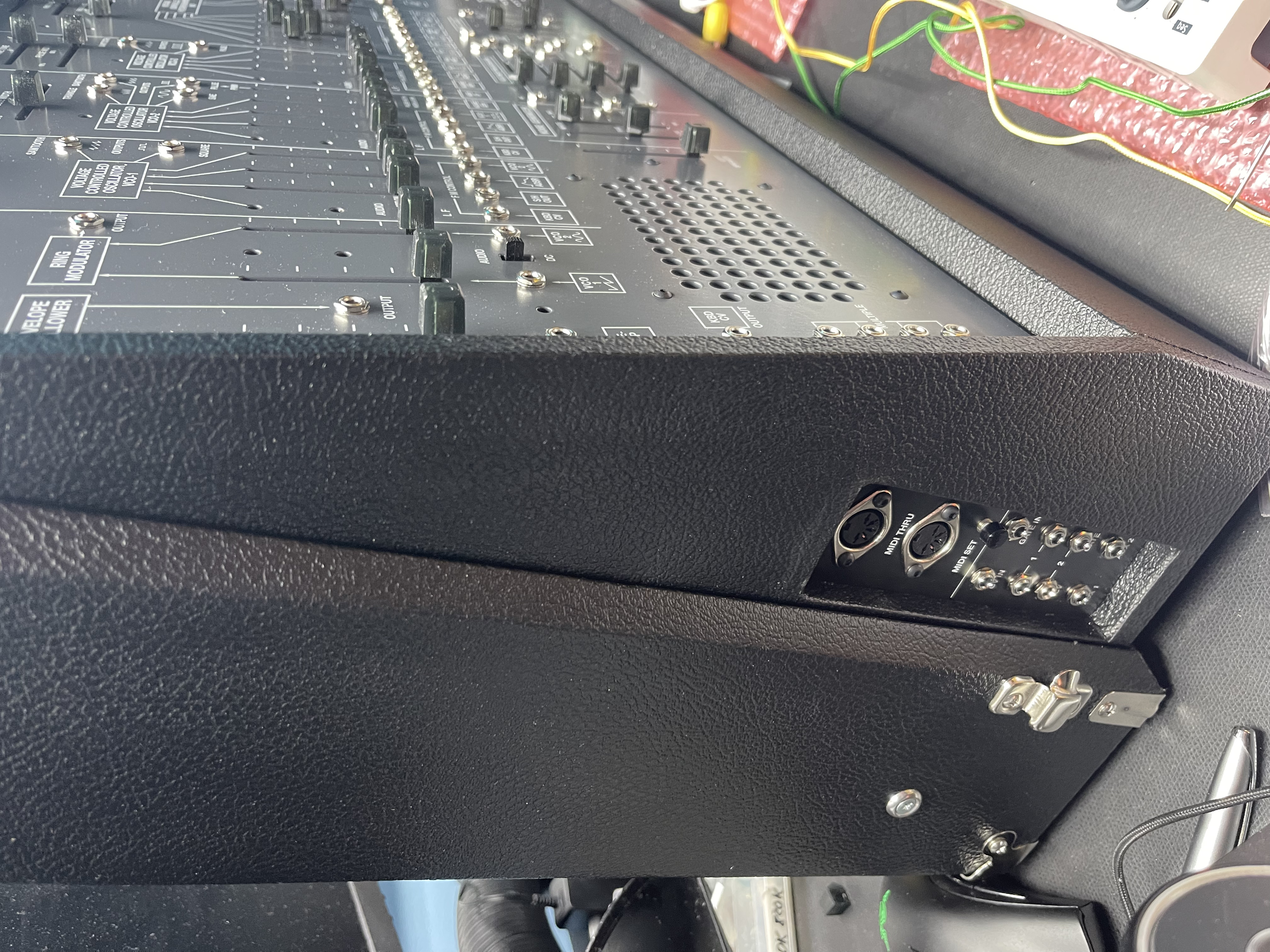
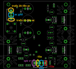
Power wiring:
Transformer wiring:

maybe you have to use 2k epoxy glue to mount the IEC inlet (was needed for my IEC model)
I connected everything in this standard way:
IEC P and N (2 cables) to > Frontpanel power switch > 2 cables to transformer PCB input
IEC earth to transformer and frontpanel ground
PSU PCB output +15/0/-15V to mainpcb
PSU PCB 3x MTA100 with drilled cable to the VCOS ! important
PSU PCB MTA156 2pole to Amplifier (double check the polarity)
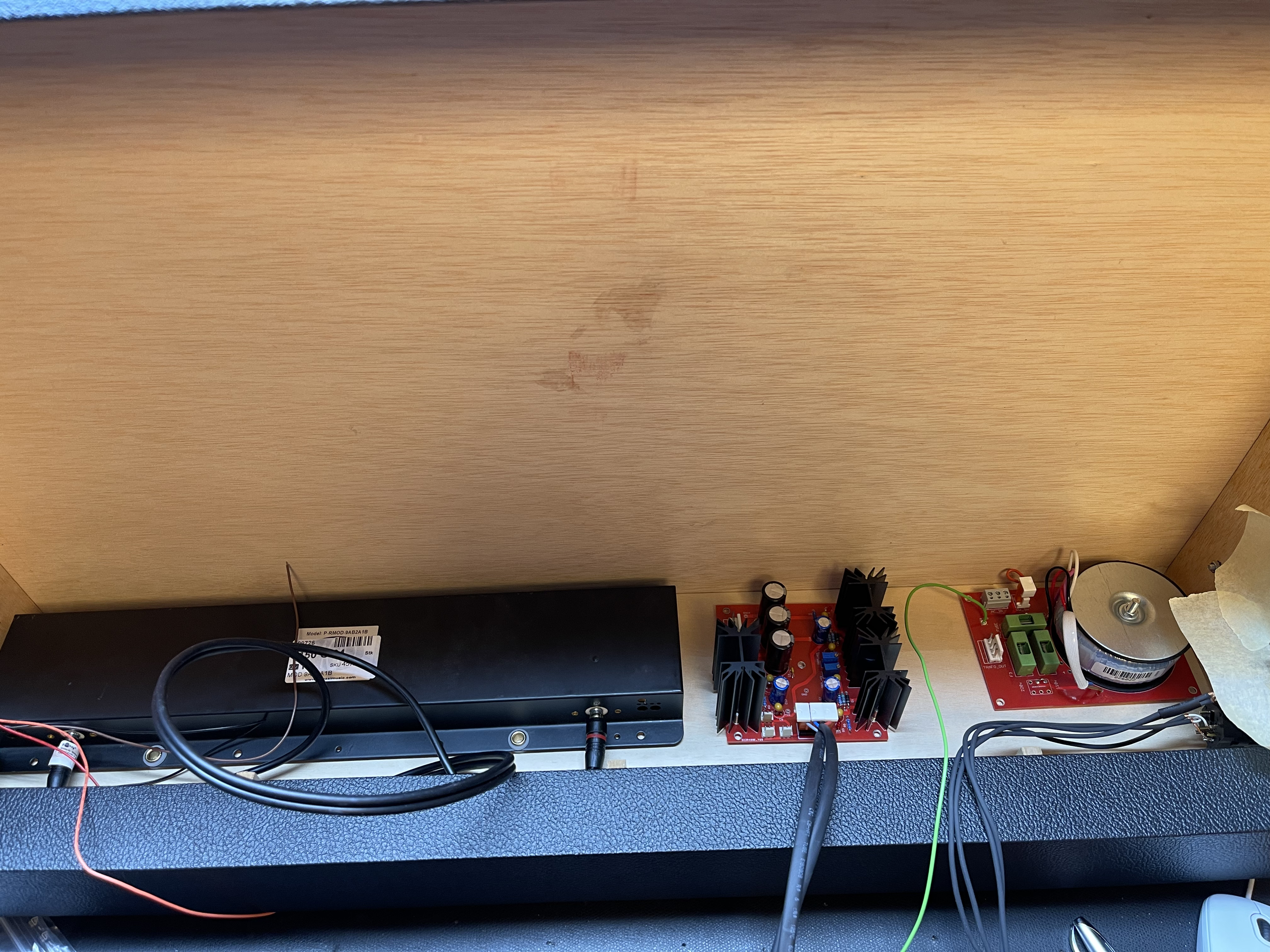
David pcbs added as shown:

Internal notes:
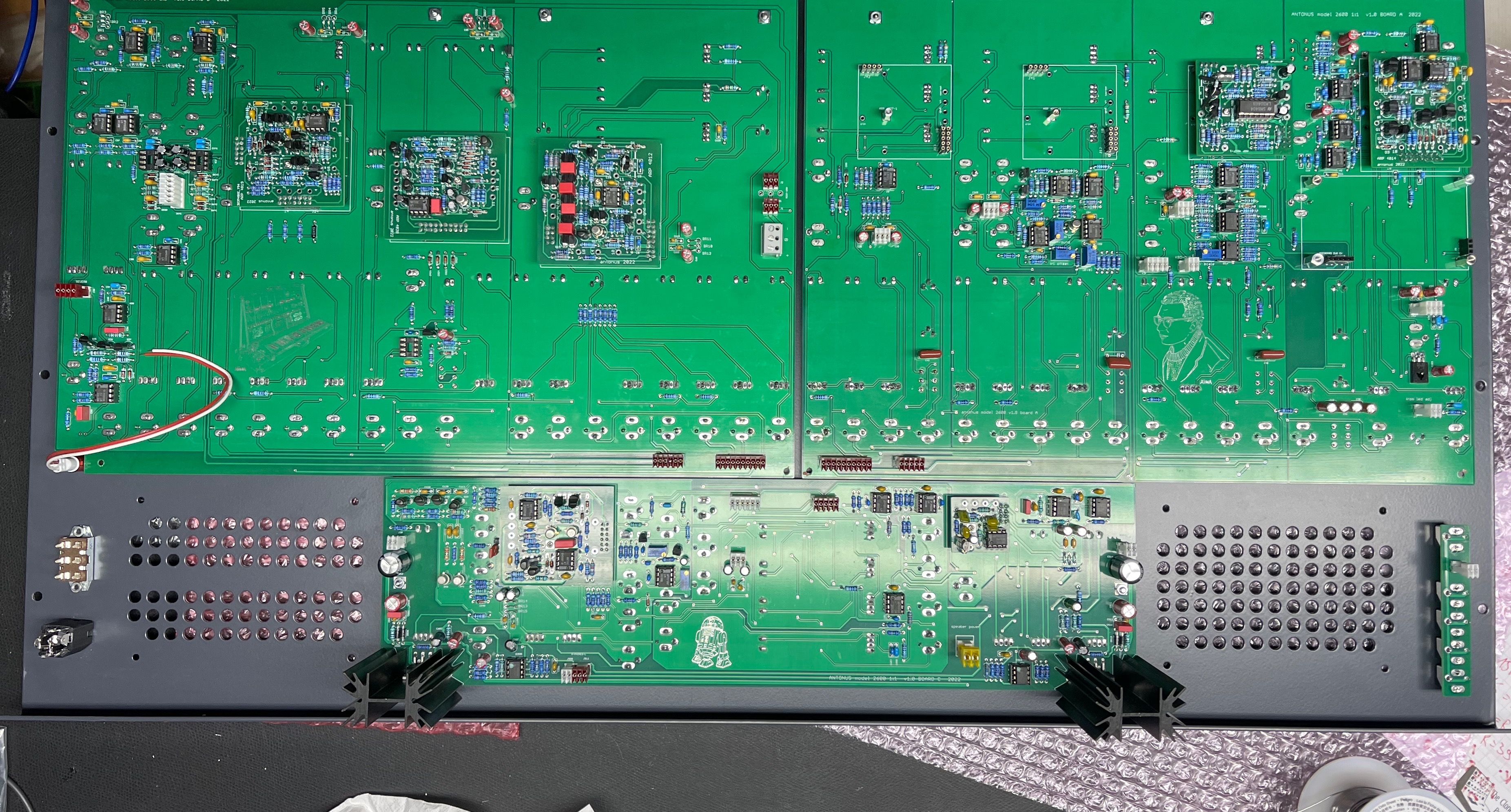
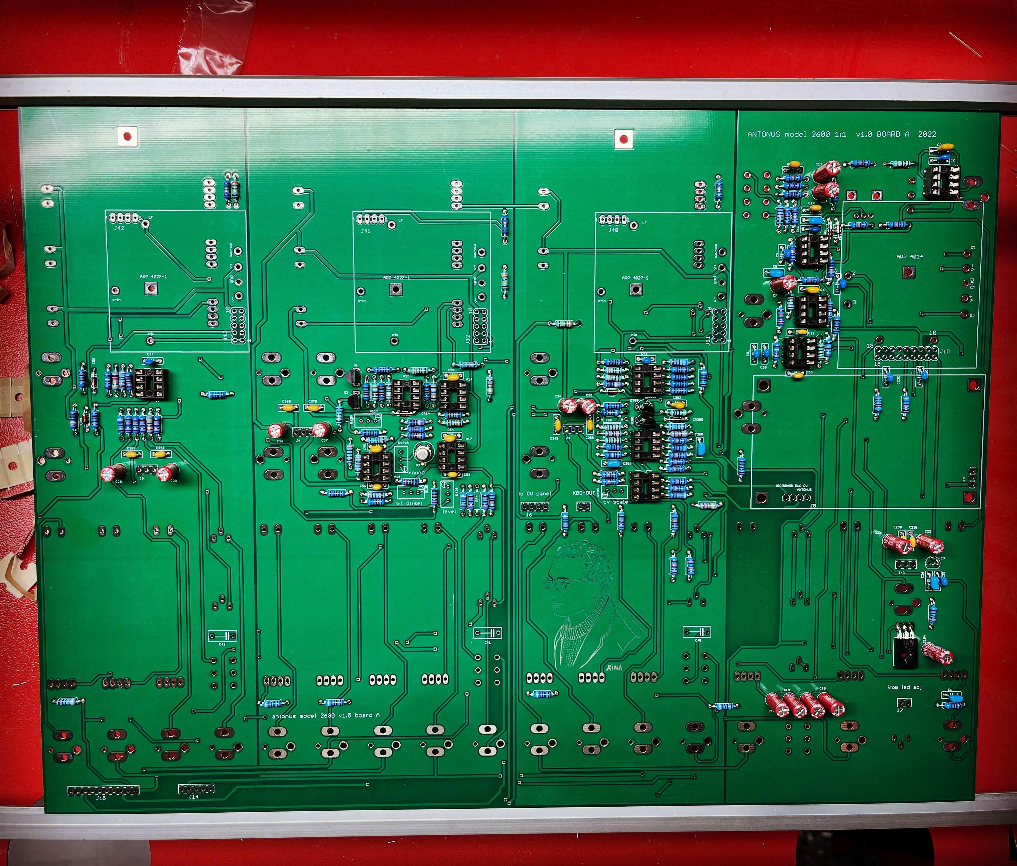
Main A: v1.0
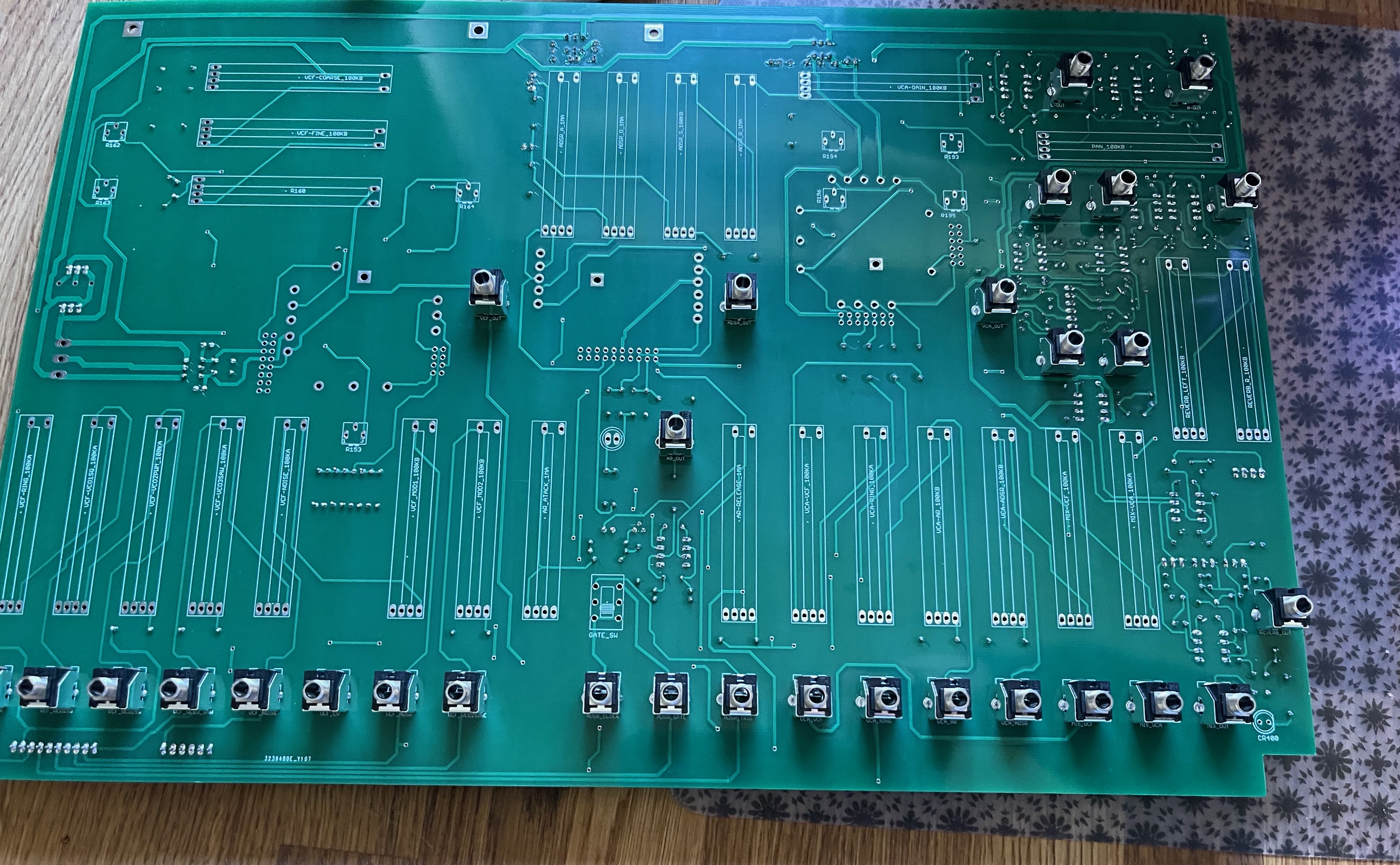
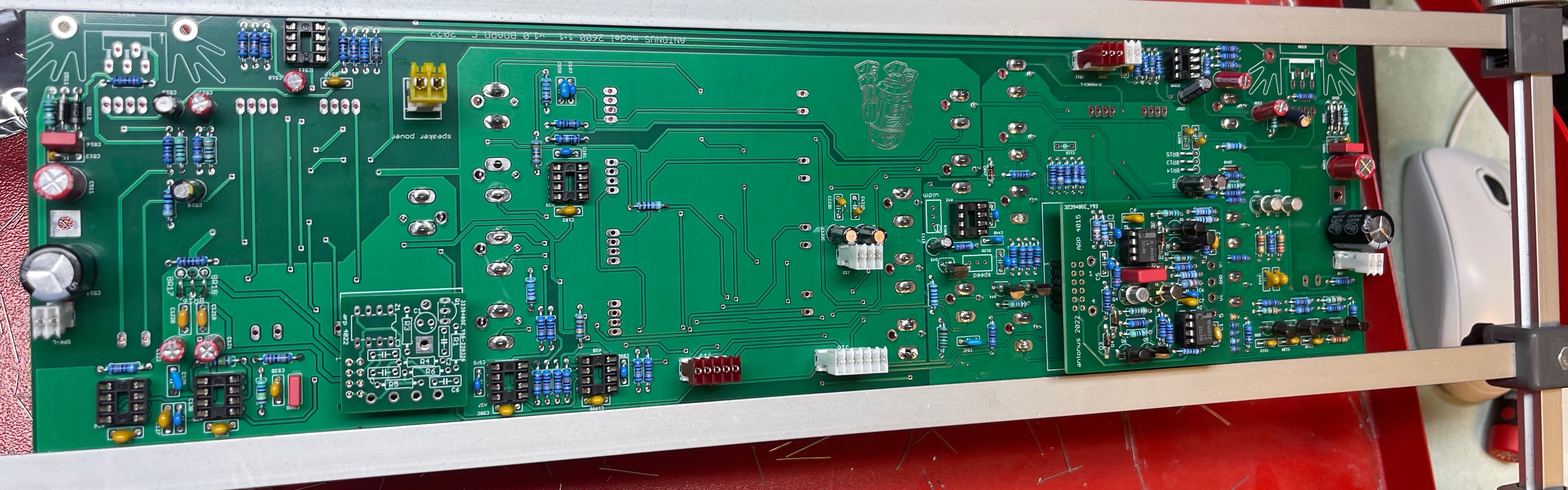
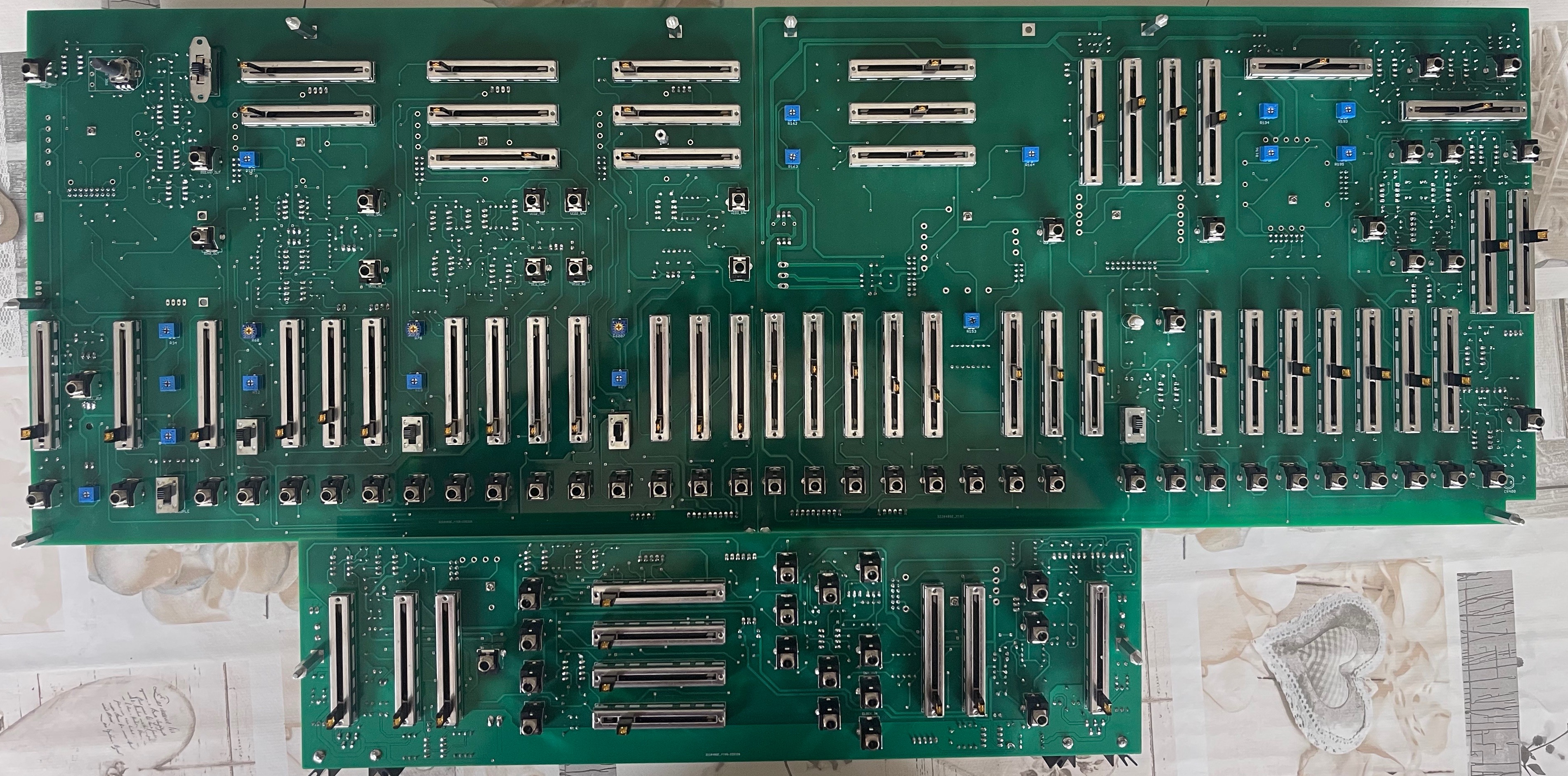
Gallery of Mainboards
...
| Gallery | ||||
|---|---|---|---|---|
|
10k added here