| Panel | ||||||||||
|---|---|---|---|---|---|---|---|---|---|---|
| ||||||||||
Projecttitel: DINSYNC RE-303Status:
Startdate: 2016Duedate: 09/2018last update : 02/2023Manufacture link: http://privat.bahnhof.se/wb447909/dinsync/re-303/Forum : http://23.235.199.139/~re303c5/forum/ |
...
MOUSER BOM project card: https://www.mouser.at/ProjectManager/ProjectDetail.aspx?AccessID=0324e99177
plus tactiles: 688-SKQEAA
| Info | ||
|---|---|---|
| ||
ift(y): yellow coil for the original cpu clock |
...
Buildguide v1.2
(source: https://shop.re-303.com/build-it/)
| View file | ||||
|---|---|---|---|---|
|
Issue/Help
| ID | Issue | Issue/Mod Description and fix |
|---|---|---|
| 1 | Gate | in case you hear the gate signal - attack clicks - you can try to connect a 100nF polar cap** between GND and Trigger. Measure with an scope to find the best value - maybe you need a bigger value 220-470nf |
Pixie CPU (the better Version)
Shop:
https://shop.re-303.com/product/pixie-powered-re-cpu/
"The Pixiepowered RE-CPU is a D650C emulator, which will allow you to run original maskrom firmware from original Roland(tm) machines."
Firmware and more:
https://github.com/sunflowr/recpu
FW manual 1.4.3
Firmware Installation (on your own risk)
- turn on and send 303.sysx with sysex librian tool
- turn off and on again
- send the boot loader sysex (1.30 version)
- turn off
- turn on while hold Step1 (all lets flashes like night rider mode)(some older boot loaders don't have the night rider mode)
- now send the REEMU 1.3.0 sysex
- machine restarts byself in 1.3.0 mode
- turn off and on the 303
- send the 303 sysx (optional)
- reload the boot loader 1.4.3 in boot loader mode (hold step1) and upload the REEMU 1.4.3 sysex
Sonicpotions CPU: (deprecated ) pls. use the Pixie CPU
Julian from Sonic Potions developed a CPU for the RE303, this CPU is also an replacement for TB-303
...
you can also use a Bassbot TT-303 case (the first 303 style case)

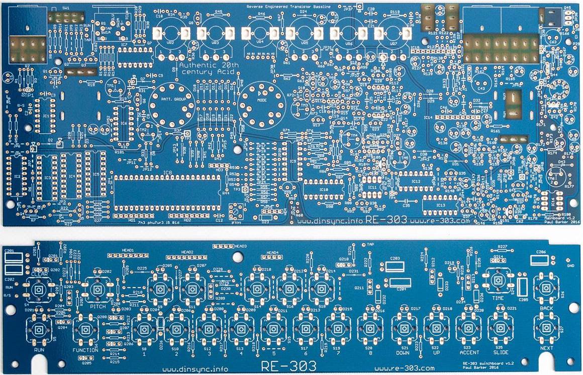
Buildguide v1.2
Modifications:
http://www.ladyada.net/make/x0xb0x/mods.html
Potentiometer Modification:
Available in my shop: (shipping starts end of June 2020)
(source: https://shopwww.re-303diysynth.comde/buildpcbs-itpanels/)
| View file | ||||
|---|---|---|---|---|
|
Case Assembly guide
RE-303_case_assembly_guide.pdf
...
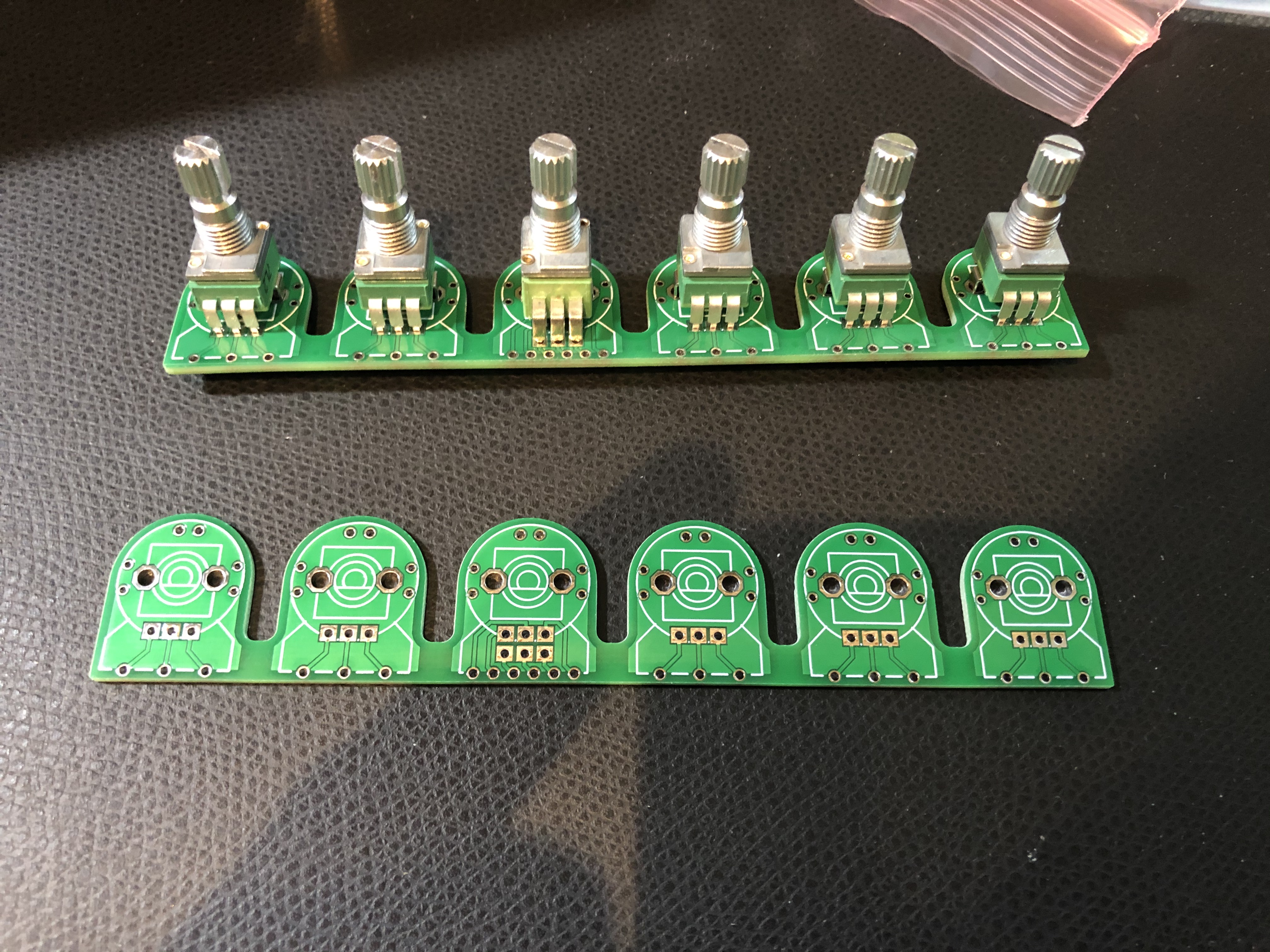
no wobbling potentiometers anymore !!!
ask me if you need/want this solution, i left some pcbs..
you also need for the Midi Jacks an adapter.
BOM:
you need one of this Stereo Pot: (VR4 in the 303)
VR4 B50K Stereo !! (linear stereo)
VR2, VR7 = 50KB (lin)
VR3, VR5 =50KA (log)
VR6 = 1MA (log)
in total 6 potentiometers
https://www.thonk.co.uk/shop/alpha-9mm-pots-vertical-t18/
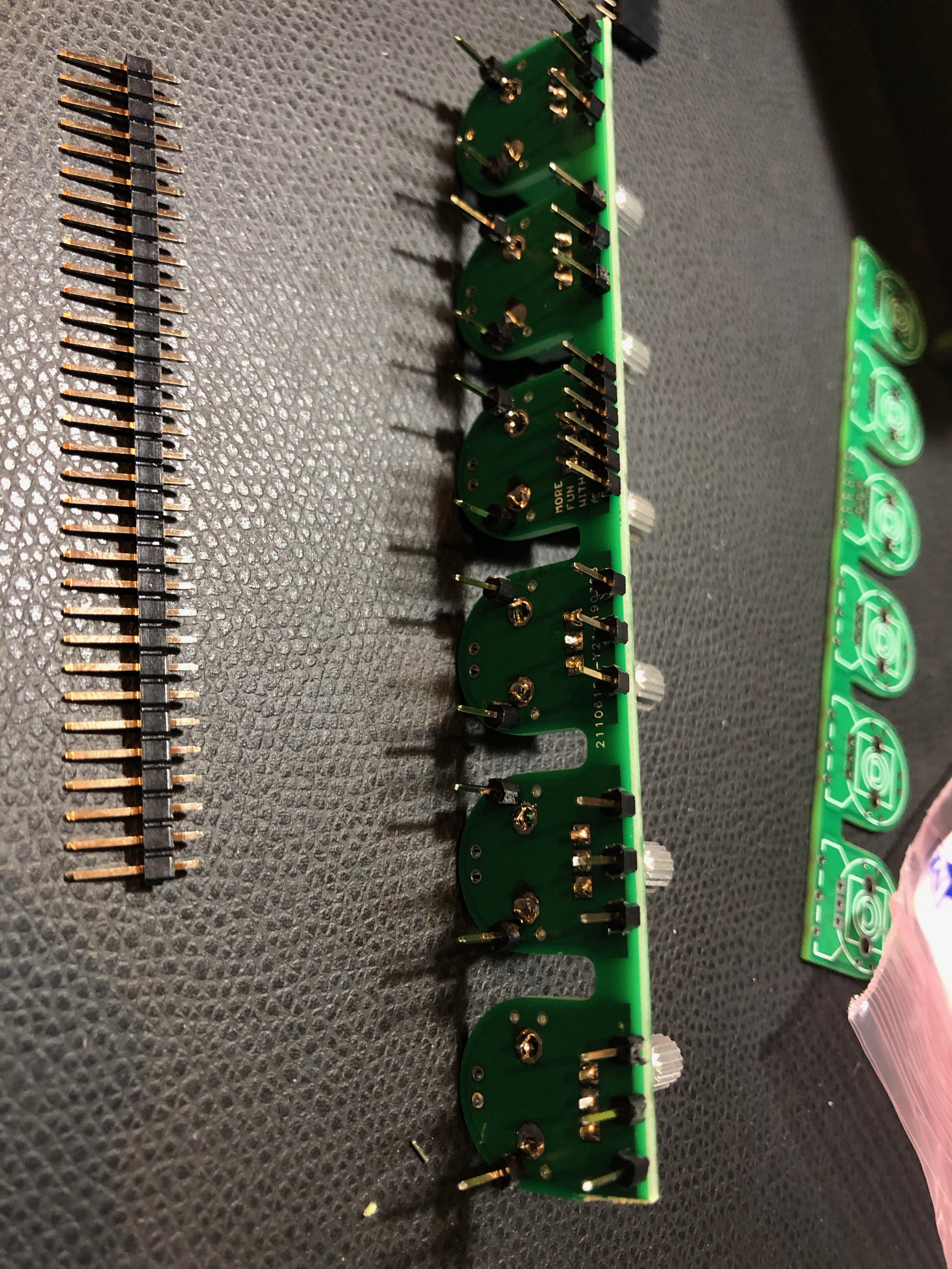
and you need:
pinstripes as shown above in my pictures.
2x 3.5mm (1/8inch) stereo jacks Lumberg KLB-4 which is available worldwide in hundreds of shops - its a quality part.
2x Adapter for the Midi holes to use the 3.5mm jacks - ONLY if you use the RE-303 Aluminum case - this are included with the PCB order in my shop !
2x 3.5mm (1/8 inch) plug to MIDI Cable - thonk or make your own.. https://www.thonk.co.uk/shop/alm-midi-trs-cable/ or DIY: NYS322 + 172-7435-E (mouser) you also need for the Midi Jacks an adapter.
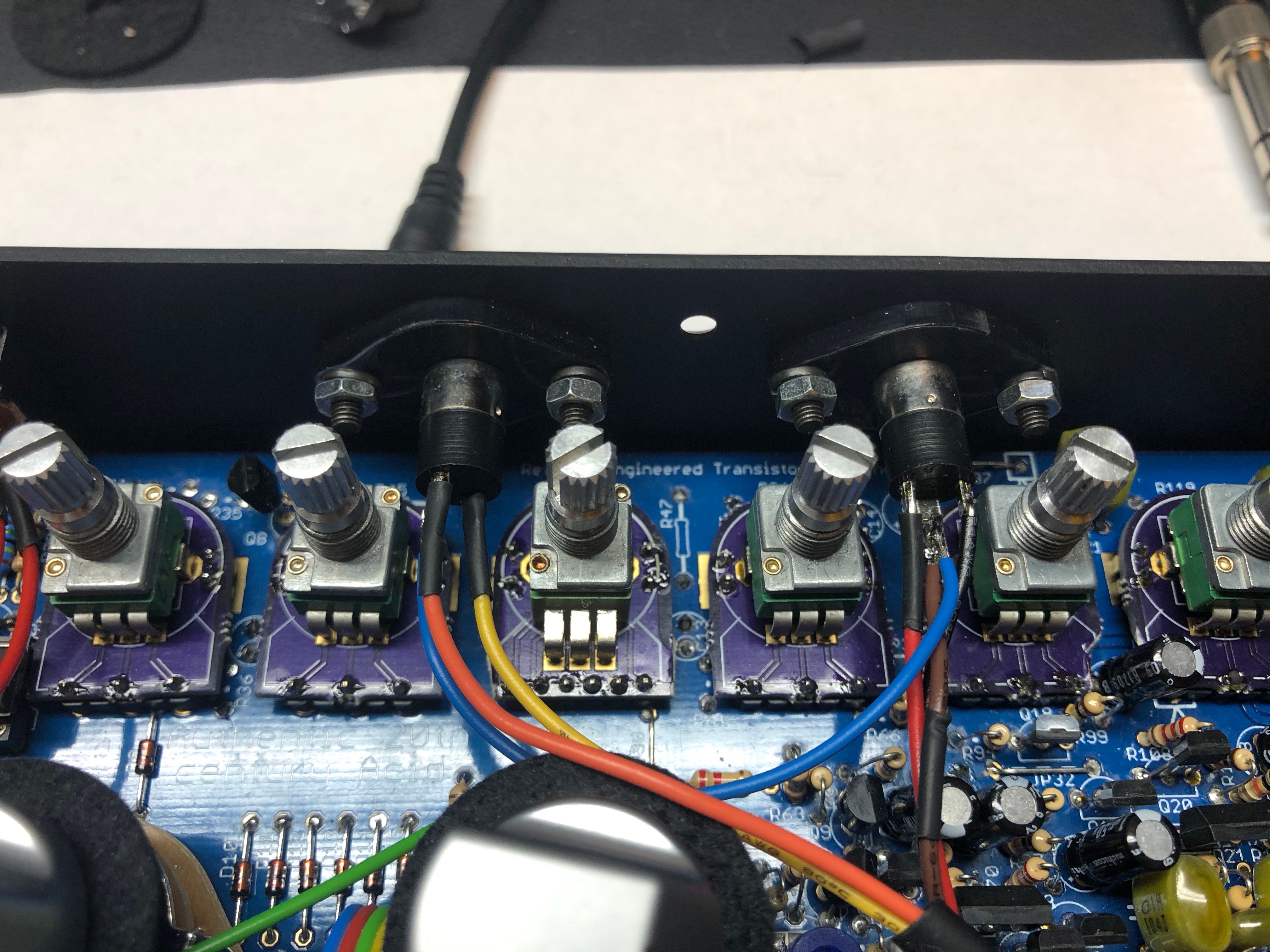
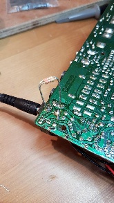
update 01/2020: ground the MIDI IN port too, that's needed because the acrylic's adapter to the stereo 3.5mm jacks are isolated
in case you use silver knobs: they are metalized and make grounding issues, you have to remove from the bottom the paint with a cutter knife.(easy)
the blue cable connects ground from MIDI out to the MIDI IN jack.

Battery Tray - optional
You will need 5x 1.2V AA batteries, get the ones from IKEA, they're from the same factory as the Eneloop ones but for a fraction of the cost.
Unless you can find a 5x AA battery tray best bet is to 3d print your own.
Then follow the official guide for installing the battery tray.
It is important to fit a 10 Ohm resistor as in this photo.
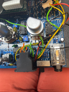
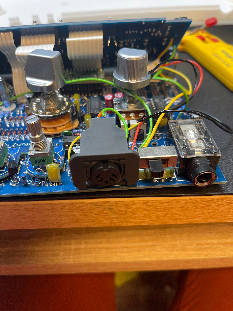
DIN JACK Connector with integrated switch
assembled versions are here:
Switching+DIN+Sync+Jack+Assembly+&+Installation.pdf
or create your own by 3D print it (SLA)
Switching DIN Sync Jack - housing.stl
Switching DIN Sync Jack - actuator.stl
- Switch: Alps Alpine SPVQ910205
- DIN 5 Jack: Multicomp PSG03463
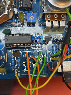
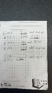
my own VCF Resonance modification:
the underlined lines are the value which I installed, you should use milled ic pins to make testing and replacement to your favorite sound easier
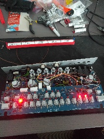
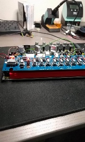
Random pics: