i built my DDRM v2 in 09/2019 (after 5 rev1. builds)
BOM
make sure you have an 6N139 instead of 6N138 in the output board or you run in an issue with stocking notes
Soldercore:
use no clean solder core, (do not use organic based flux based core)
...
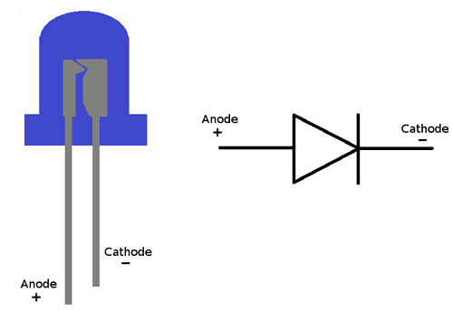
normal LEDs are as shown, when you look in your LED - you can see a long and short part inside.. that's not happen on our LEDs from the mouser BOM !! please check it
positive is the square pad on the PCB !!! m short leg is the flat end of the pcb silk (there's a circle with a flat end on the pcb printed)
Breakoutboard:
for the LED: the Mouser LEDs don't follow the standard pinout !!! - the long leg is negativ
...
use hot water for no clean solder core, otherwise isoporopyl.
Powersuply Warning
don't mix the external PSU bricks or you destroy your Device.
The Kijimi use a 24V DC PSU
DDRM v1 DIY use a 12V DC PSU
DDRM v2 DIY use a 12V DC PSU
NO SOUND BUG
The 2pin MTA100 header on the mainboard close to the PSU Slot is wrong labeled, ground and SIG is in wrong orientation (GND = SIG, SIG is GND)