...
You would wire the Spread CV jack to the input of the Spread CV Pot. Then the Wiper of the Spread CV pot would go to the switched inputs of Filter 1 CV input and Filter 2 inverted CV input.
Oh and of course ground to the 3rd lug of the Spread Pot and the Spread jack.
A 100k Pot like the other CV inputs will be fine
from Scott:
Sorry for the lack of documentation on that. You use the switch for the inversion of the CV. The spread pot is an attenuator (100k is good) for the spread jack. From the wiper of the pot, send one wire to CVSN on filter A via a 100k resistor, and one to the junction of the 100k, 2k2 and pin 3 of that TL072 (where the negative CV is going) of filter B. This will apply the spread voltage positively to filter A and negatively to filter B.
from cgs:
It has been suggested that connecting the frequency pot between +VE and -VE instead of +VE and GND as shown will allow the filter to be used at lower frequencies. If doing this, you may find it beneficial to change the wiper resistor up to 270k, or add an extra resistor of 150k in series with the wire from the wiper to the PCB.
user:
I took some advice and wired the frequency pots +V and -V instead of +V and Gnd. The filter works fine now. I'm going to experiment with limiting the range of the frequency pots.
...
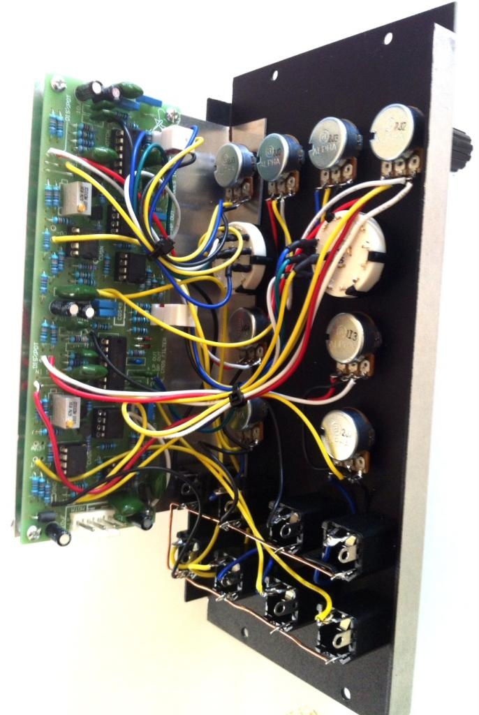
In this build, you can see the correct wiring from freq. pot to -15V on power connector
Further
...
Troubleshooting 07.01.2014
have connected the frequency pots to -VE and +VE instead of GND and +VE.
...
next step: ordering 2x new cd4069UBE oder HEF4069UBE (unbuffered)
Further Troubleshooting 12.01.2014
new CD4069UBE shows same issue.. LP dont work
todo:
solder 150k resistor to freq.pot
test/swap 1N capaciator or unswap CD4096 and measure resistor between Pin5 and Pin6 on CD4069.
solder 100k in cv-spread..