TTSH Mod Sync Option
from Muffwiggler thanks to all supporters specially "Altitude" and "sduck"
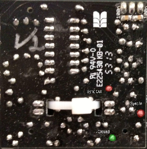
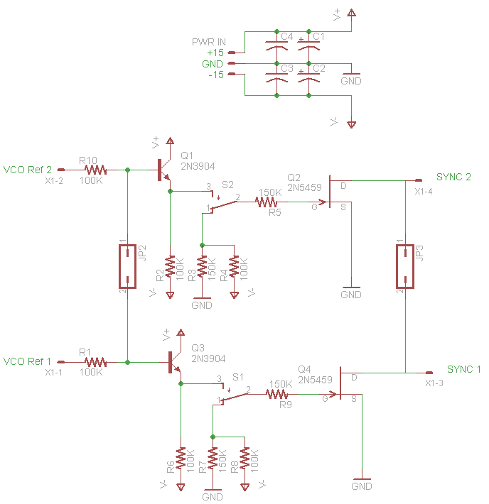
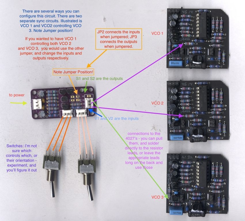
i prefer Sync: for syncing VCO 3 to VCO2 and VCO1 jumper (set a bridge) JP2, V1 = out from VCO3(61k9 resistor), S1 to VCO1 sync input, S2 to VCO2 sync input (at input = 1k5 resistor)
This MOD works in TTSH rev.1, rev.2, rev.3 8pcb version 7-8.x)
its very important to use shielded cable for VCO I/O connections to the sub vco boards (dont forget to ground the shield ob both sides)
About the wiring to switches, do not twist the cables, otherwise you get softsync issues.
don‘t twist the cables for the switches ! or you get some soft sync.
its a difficult MOD and there´re few risk to destroy your rare trannys of the VCO Cores (2N4125, 2n5459, CA3046) if you do it wrong.
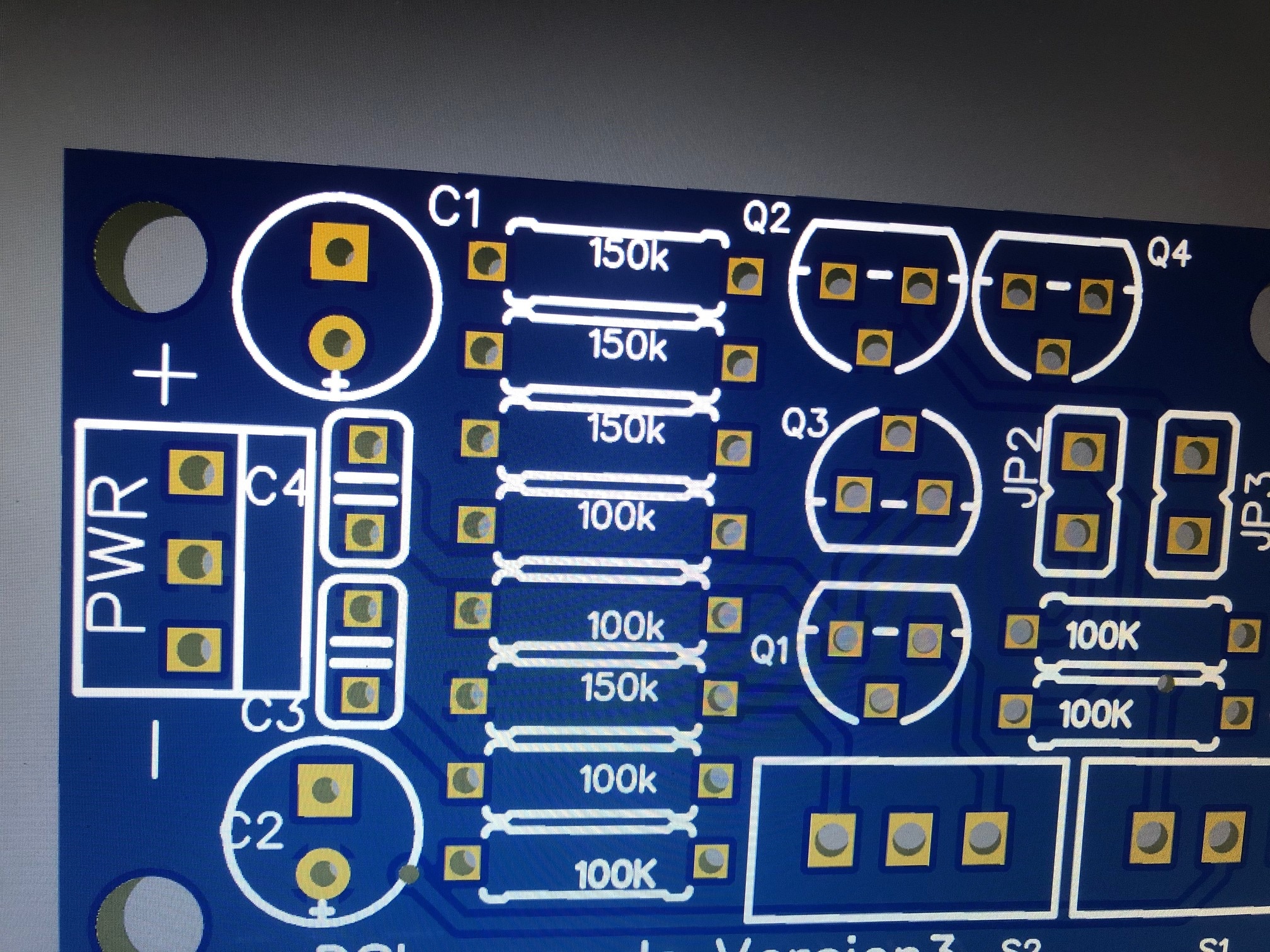
for all users who got my TTSH SYNC PCB, only use the resistor values as shown (the VCO SYNC Version2 PCB use a different PCB designator layout)
| BOM |
|---|
6x 100k resistors 4x 150k 2x 2N3904 2x 2N5459 2x 100nf X7R bypass cap MLCC 2x 10uf electrolyt cap 3 x MTA100 power header and jack 3 pin 2x 2pin mta or 1x 4 pin mta header/jack spacers, screws, nuts shielded cables RG174 cables for power, switch 2x switches (UM 3pole) |
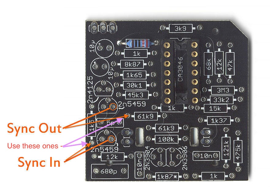
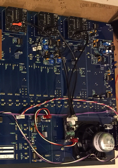
Thanks to Steve (sduck) for sharing this helpful picture:
3 Comments
Gregory Delabelle
Can somebody post a picture where the 2 switches will be placed on the panel please?
Getz
Here you go,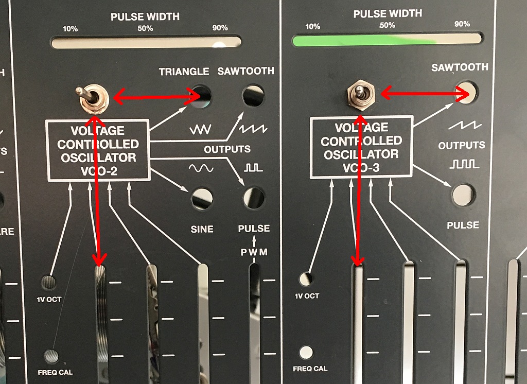
Bill Cole
Not sure if it's just a grammar issue, but when I read
I understood that as using VCO1/2 as SOURCES and VCO3 as sync destination. However, the jumper and wiring indicate that VCO3 is the source and the other two VCOs are the sync destinations. Can you clarify the intended meaning?