Successful Build : 04/2019
tech:
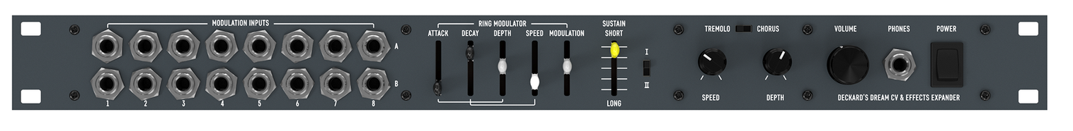
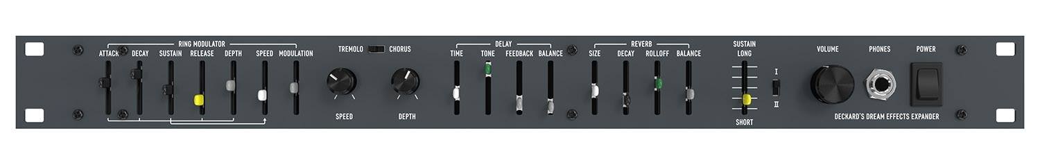
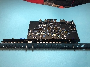
it adds an envelope controllable Ring Modulator, Chorus, Tremolo, Delay, and Reverb effects. It is designed to work seamlessly with Deckard’s Dream, but it also works as a standalone audio effects device.
Schematics:
DD-EXPANDER-SCHEMATICS-REV1.zip for rev.1.0
BOM:
DD-EXP-BOM-REV1.0.1.pdf latest version for rev.1.0 and YOU MUST ADD 2x TL071 and 1x 4.7uF MLCC capacitor RM5DD-EXP-BOM-REV1.0.0.xlsx (Old version) for rev.1.0
![]()
BOM LATEST BOARD VERSION INFO
rev.1.1 changes
the new PCB Version is 1.1 !! (midi noise fixed)
it use following changes which affect the above BOM, you have to respect this:
IC33 and IC37 is TL071 (DIP8)
C166 not in BOM 4.7uF ceramic (MLCC) RM5
latest firmware
It's for all Expander versions
DDRM Expander VC Placement Guide V2 from Kevin Looney:
DDRM Expander VC Placement Guide V2.pdf
DDRM FAQ and Build tipps from Todd
Deckard’s Dream Expander FAQ and Build Guide V1-7.docx
Trimmer Values (was requested by a user)
SIG= 501 = 500Ohm
REF: 201 = 200R
0.2Khz =103 = 10K
2.5k = 103 = 10K
Further Build Infos (was requested by a user)
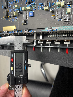
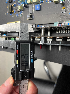
Distance between Panel and Slider/control PCB = 10mm
Distance between Controlpcb and analog pcb = 12mm
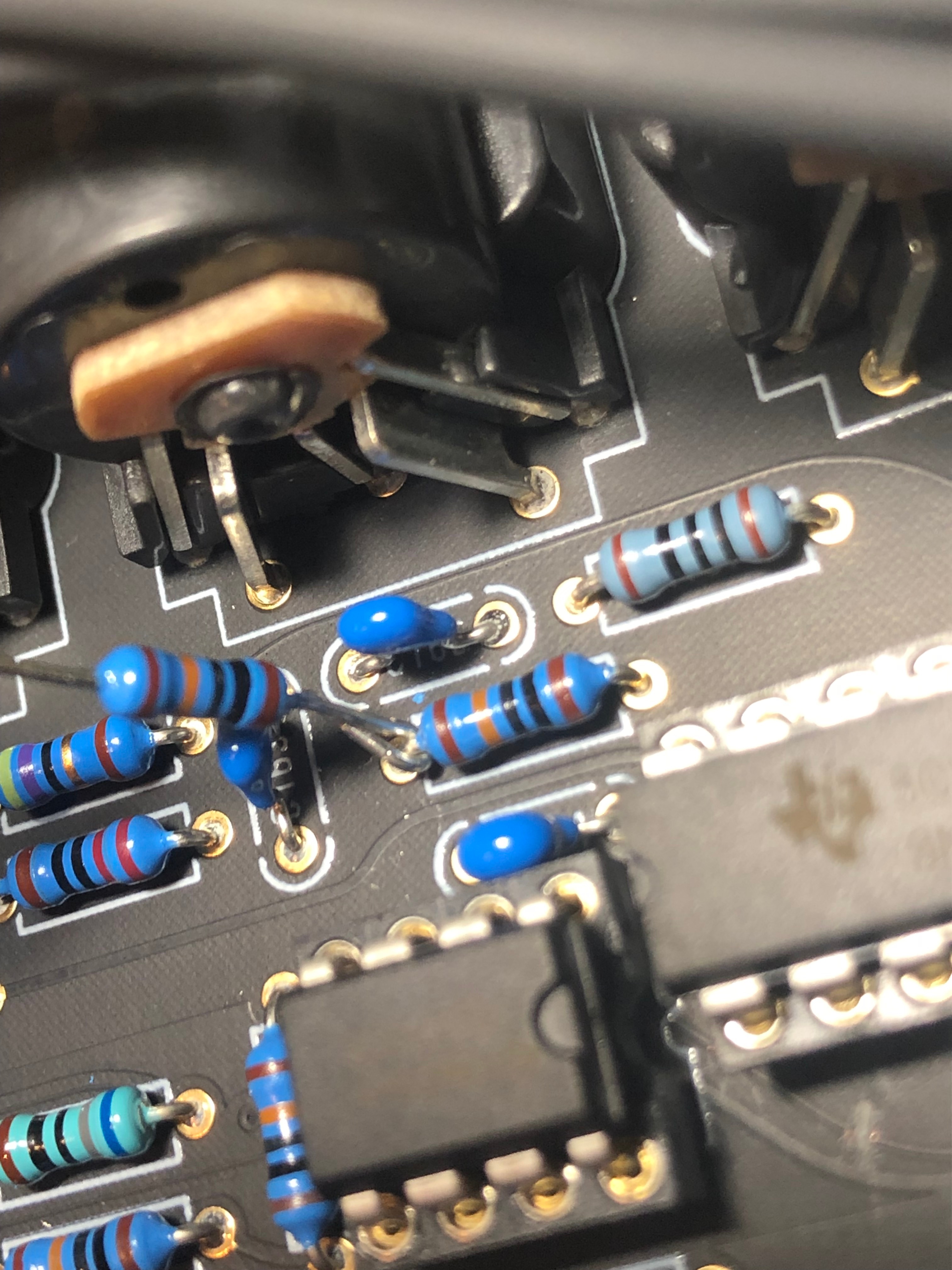
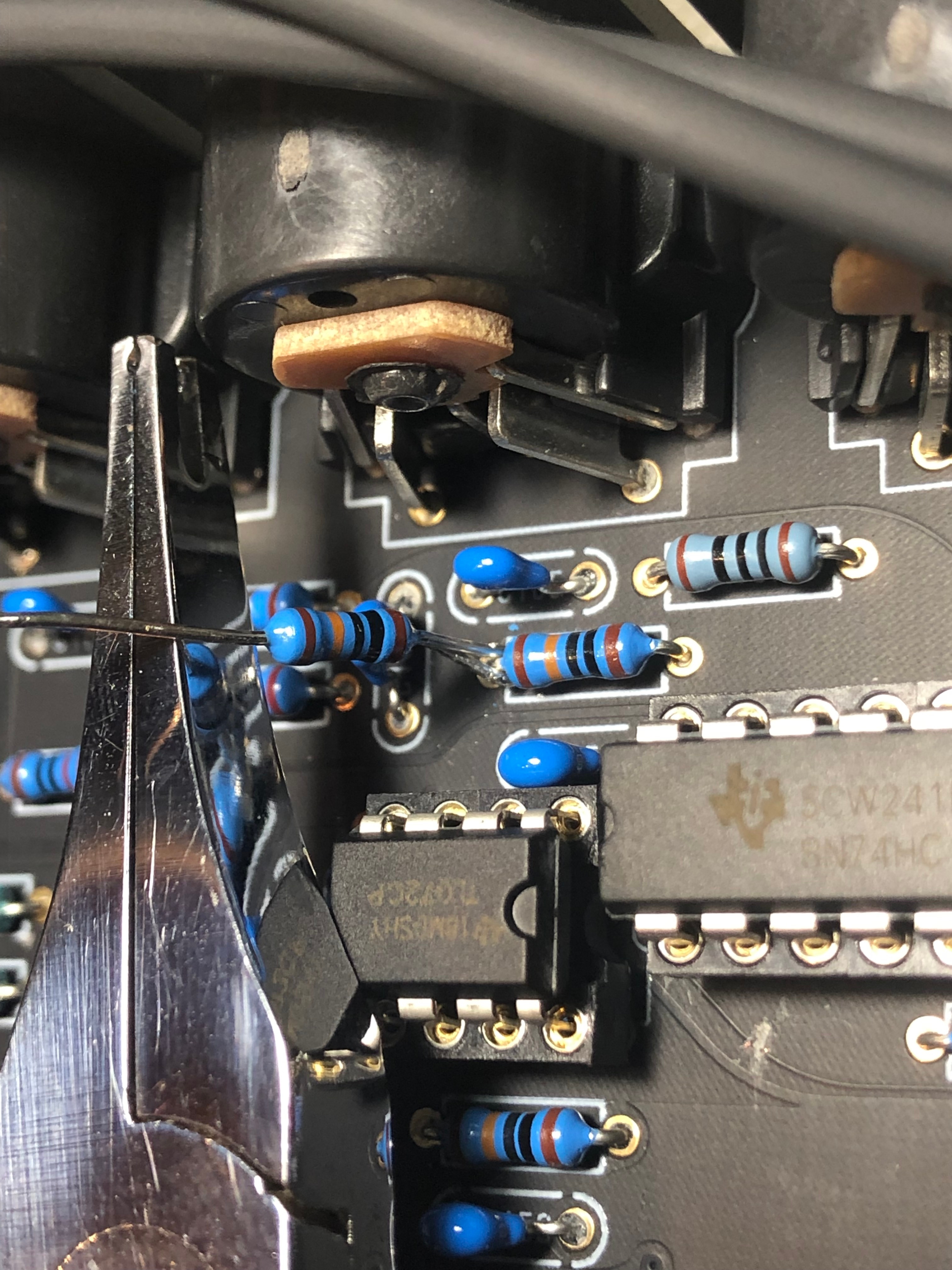
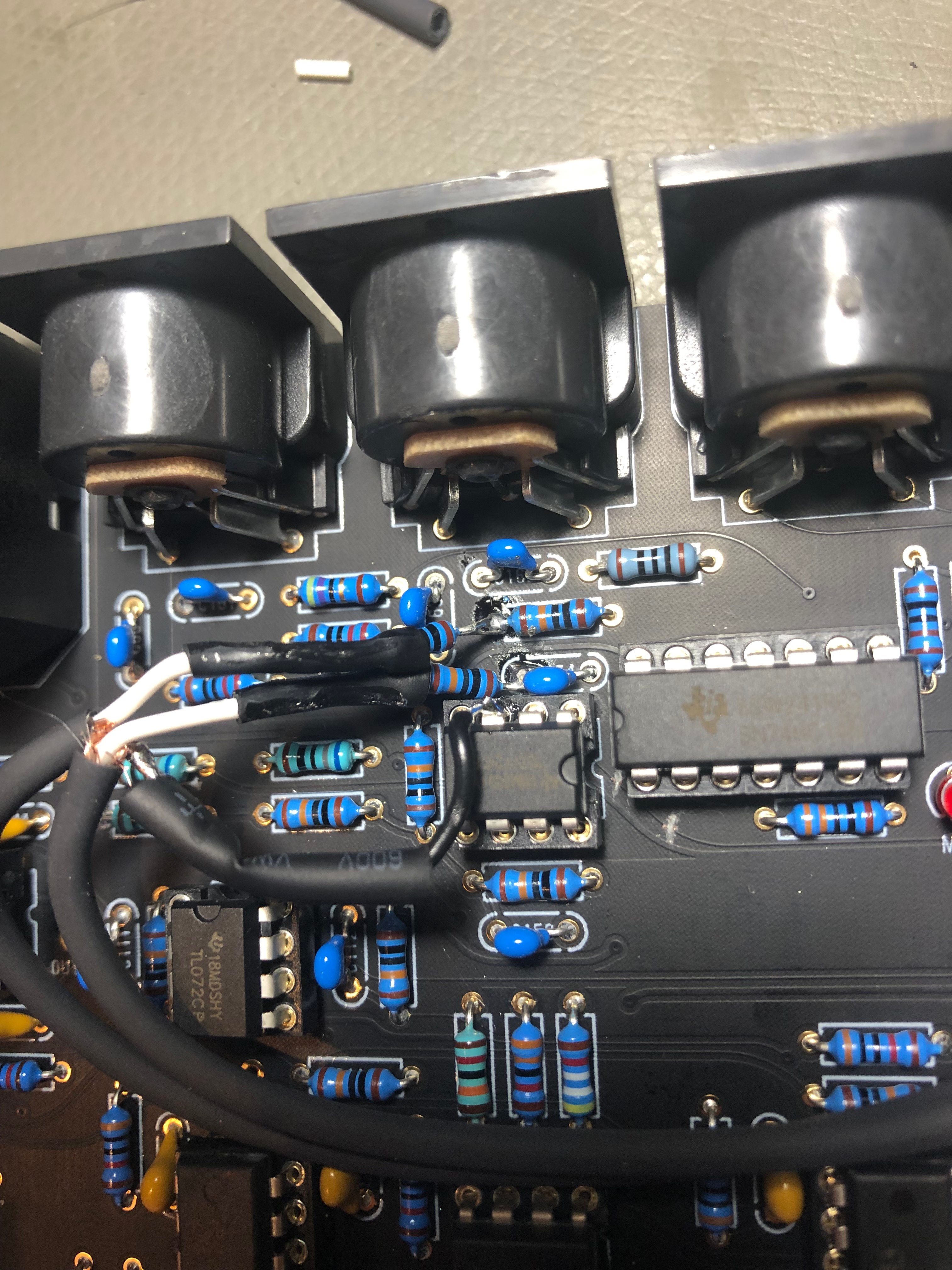
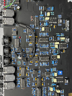
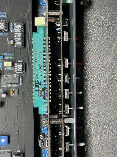
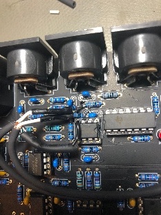
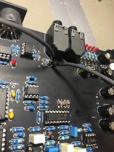
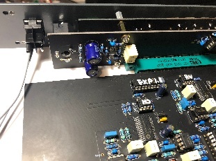
MIDI-NOISE FIX pictures:
only for DIY PCB Version 1.0
is fixed in DIY PCB Version 1.1
If you want a fix of your factory assembled Version, contact me
Click expand for Pictures from rev1.0 pcb Modification FIX

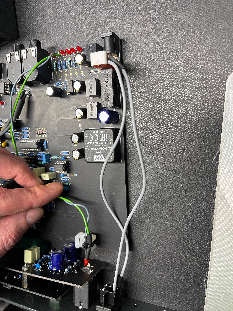
Addional pics 2021:
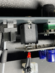
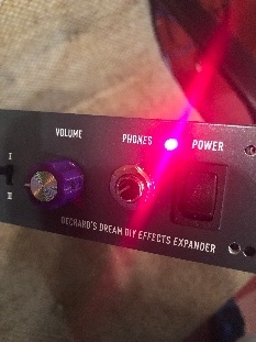
Power LED Installation:
remove the 12V LED from the Card PCB and drill a 4,5mm hole in the frontpanel - which is the standard size for 3mm LED-holders (available in most electronic shops)

psu DC-DC alternative part:
DKMW30F-12 meanwell (approval ![]() - tested
- tested ![]() )
)
The DSP chip, potentiometer, AS3310, As3340 from Musikding too ![]() confirmed
confirmed
Case: 169 USD
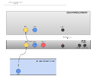
First Design Concept:
Final:
|
|
|
|
|
|
|
|
|
|
|
|
|

|
|
GLIFFY IMAGE
|
||
|

|

|
|
|
|
|
|
|
|
|
||
7 Comments
Thom K.Wait
I got the DDRM expander (ready build smd version) 2weeks ago, first jams where real cool....
But after some jamming I found several weak points and was then realising that the unit is far from perfect...
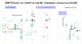
I decided to add: A LED showing the ADSR Envelope, A power LED and a very helpful overload LED to signal any overload of any of the three FX chips (FV-1 Pin5)
(see the schematics for the LED mods below)
Unfortunately during my lab investigations I found more...
But now to mention the good things
Possible future Improvements (my personal favourites)
Joan Touzet
The MCU's (PIC16F1805) 1.1 firmware has a bug, where the frequency of the ring mod follows the "Sustain" slider but never releases. This can be verified by monitoring the RA0/ICSPDAT line on the PIC - this starts at 0V at power-on, but as soon as any MIDI note is received it goes high to 3.3V and never drops. It should go low after the note is released, following MIDI sustain rules.
Version 1.5 of the PIC resolves this - the file as provided by Black Corp is available here. The original PIC can be programmed with a PICkit3, or via an Arduino using this GitHub project.
Ian E Shepherd
Hit a couple of queries (so far):
Thom K.Wait
Ian E Shepherd
Thanks TKW! All fine - so far! Does anyone out there have a setup document or any information regarding the setting of the pcb presets?] I am struggling to find any information or suggestions for testing.
Ian E Shepherd
Help required, please! I am testing the expander card board power rails. I cannot obtain -5V. I have IC2 (TL071) in place and 5V at R3 hot end. About 3v at pin 2 of IC2 - less than 1.5v at -5V pad. and LED not lit. R1 and R3 are correct at 100K TL071 swapped for another - still no -5V!
Any suggestions please?
Ian E Shepherd
Previous problem identified, I think! Obvious really that until the TL071 has 12V applied it will not complete the voltage inversion.
Awaiting on DC-DC converter to obtain the 12+ and -